- 7 -
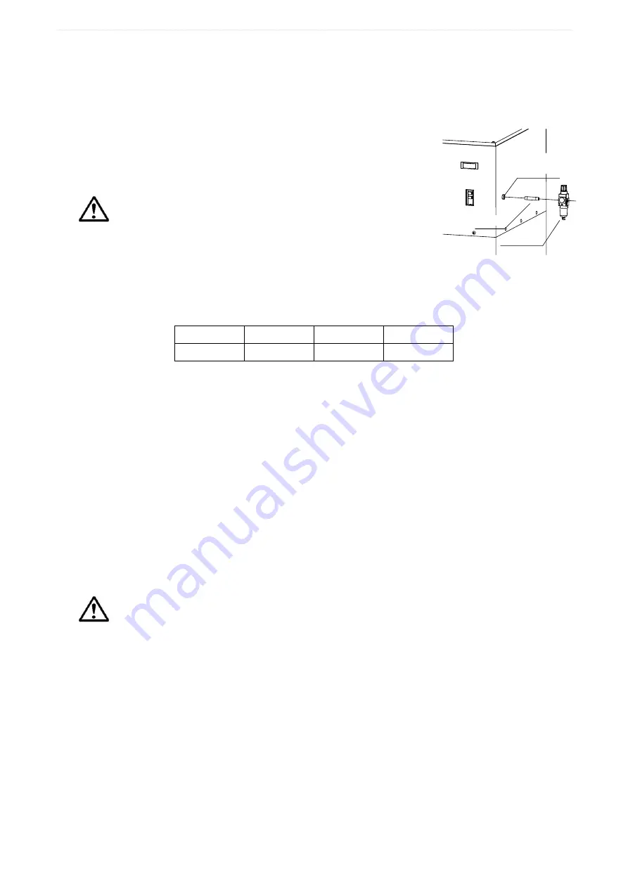
エアー接続口
(Rc 1/4)
ニップル
FRユニット
Air piping
Attach the accessory nipple and FR unit to the air connection port on the machine’s flank for
the connection of compressed air. Since the FR unit has a specified airflow direction as
indicated with an arrow mark which should be followed when installing the unit.
The air connection port, which is factory-set on the right flank
of the machine, can be changed to be set on its left flank by
changing the internal configuration. Location of the FR unit
pressure gauge may also be changed from the back to the
front of the machine.
Compressed air must be free from an oil and water mixture.
Oil and water deposited on the filter cloth will blind it.
Set the air pressure for 0.5 to 0.7 MPa by operating the
handle on the upper part of the FR unit; lift up and turn it to
change the settings and push it back when done.
Note: 0.1 MPa = 1 kg/cm
2
Choose a desired compressor capacity and piping diameter by referring to the air
consumptions in the following table:
CFM-H10 CFM-H20 CFM-H30 CFM-H40
40 L/min
50 L/min
60 L/min
80 L/min
Note: The listed air consumptions are based on the conversion into atmospheric pressures on the
assumption that pulsation is activated twice per minute at 0.6 MPa.
Hood and connection of the duct
Dust collection method and suction air speed (controlled air speed) may vary depending on
the kind of dust and the condition of scattered dust. Generally, the suction air speed in the
hood opening vicinity should be designed to be 0.5 m/sec. or faster. Also, it is desirable that
the airflow in the duct is 15 m/sec. or higher.
The duct piping should be air-tight with no suction or leakage through the joints.
Use supports and expansion joints to prevent any direct duct load from being applied on the
machine.
In case a flexible duct is used, it should not be bent too sharp or unnecessarily sagged so it
may keep a high suction power.
The suction port, factory-set on the right flank of the machine, can be changed to be set on its
left flank. Interchange the suction cover and the suction port.
Although no exhaust duct is required in most cases, install the duct where necessary.
In case a duct is to be installed on the exhaust outlet, make it as short as possible. This is
because, with a large load applied on the exhaust side, not only the suction power is
weakened but also air leaks could occur in the switch section or other portions. Also, caulk the
place around the ceiling panels to prevent air leakage.
Design the exhaust duct so it may be readily detached for maintenance.
For detailed information about the choosing of hoods and ducts, please call our nearby branch/sales office.
Trial operation
Before a trial run of the dust collector, make sure:
• that the installed machine has no backlash or play;
• that the power supply cable, earth cable, insulation and voltage have been arranged as
specified;
• that no leak occurs at the air joints or no bolts, tools, etc. are left behind in the duct;
• that the maintenance door is securely closed;
Air connection port
Nipple
FR unit


