background image

Step 7


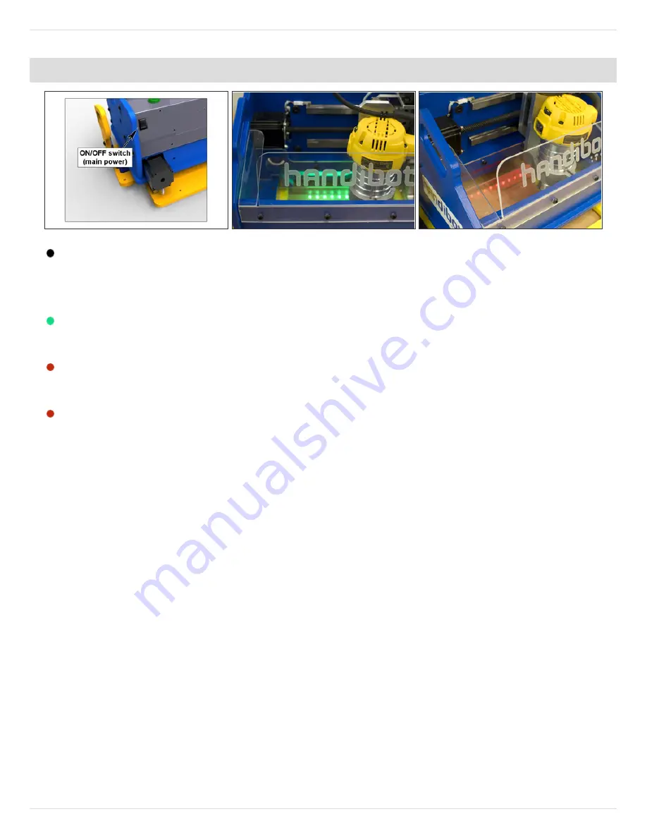
Turn the Handibot on using the main power switch on the back of the machine. Keep in
mind that there is also a power switch on top of the router, which will need to be turned on
before you cut anything.
With the main power switch on, you should see a line of green LED lights inside the work
area. This indicates that the Handibot is "ready to work."
When the motors are moving, you will see a line of rapidly blinking red LEDs. This is a
warning light to keep hands and stray objects away from the work area.
When the router is activated by a part file or in keypad mode, the red LEDs will start
blinking slowly.

HandiBot Setup Guide

© 2014

shopbot.dozuki.com

Page 7 of 15

Summary of Contents for HandiBot

Page 1: ...ShopBot Tools Inc Handibot User s Guide This is a guide for app developers and other first adopters of our HandiBot Tool It provides an introduction to our control software and the basic functions of the Tool ...

Page 2: ...entals Inserting a router bit Zeroing the Z axis Zeroing the X and Y axes Ready to cut 2 Control software screen reference chart 3 Choosing the right bit for your project Types of bits Calculating cut speed and RPM using Chip Load values 4 Holding down material for cutting Please note this document was written for our full size tools some hold down methods may not apply to use with a HandiBot ...

Page 3: ...HandiBot Setup Guide Written By ShopBot Tools HandiBot Setup Guide 2014 shopbot dozuki com Page 1 of 15 ...

Page 4: ... before changing bits or placing your hands near the router Never wear gloves when operating the Handibot Gloves can get caught in rotating parts and pull your hand into the cutter Never leave the machine running and unattended A spinning cutter generates friction which is a fire hazard Keep a fire extinguisher in your work area Take time to learn about and understand this tool before using it Do ...

Page 5: ...ur tool as well as the location of XY 0 0 This is also referred to as the home position We ll explain this further once you have the software installed and can control the machine using your computer Step 3 Handibot anatomy rear Take a moment to familiarize yourself with the major components of your Handibot We will refer to the tool using these terms so they are helpful to know HandiBot Setup Gui...

Page 6: ...king for a blue outline or SS SuperSpeed logo near the port Locate the ShopBot USB drive that came with your HandiBot and plug it into your computer Alternatively you should have received an email containing a link to download the software Do not plug the USB cable from your Handibot into your computer until instructed to do so in Step 5 Open the install_shopbot exe file Follow the on screen promp...

Page 7: ...lows you to read and directly edit ShopBot part files VCarve Pro ShopBot Edition is a 2D CAD CAM program that enables you to design parts import vectors apply toolpaths and create part files that your Handibot can cut Partworks 3D is a 3D CAM program It allows you to import a 3D model that was created in another program and apply toolpaths to create a part file HandiBot Setup Guide 2014 shopbot do...

Page 8: ...lug into the wall and you re almost ready to go However we do not recommend plugging it into a GFCI ground fault circuit interrupter outlet These are commonly found in kitchens bathrooms garages and outdoors Plug the Handibot s USB cable into your computer HandiBot Setup Guide 2014 shopbot dozuki com Page 6 of 15 ...

Page 9: ...h on you should see a line of green LED lights inside the work area This indicates that the Handibot is ready to work When the motors are moving you will see a line of rapidly blinking red LEDs This is a warning light to keep hands and stray objects away from the work area When the router is activated by a part file or in keypad mode the red LEDs will start blinking slowly HandiBot Setup Guide 201...

Page 10: ...ogram you will be prompted to load a settings file for the machine Click OK when prompted then select Handibot and click Open This will load all the correct settings for your Handibot Step 9 If you aren t prompted to load your settings file or if you need to reload them in the future you can do so by navigating to the Utilities drop down menu and choosing Reset Default Settings HandiBot Setup Guid...

Page 11: ...ls drop down menu and select ShopBot Setup When the popup box appears click next At the bottom of the next window check the box next to I have prox switches and uncheck all the others Step 11 Select the option I like doing things the hard way Toward the bottom of the page change the values for the X and Y switch offset distances to 05 Click Next then on the subsequent screen click I m done HandiBo...

Page 12: ... functionality of the software for the coming steps Click the blue question mark button shown here then choose Switch to FULL Step 13 Once you enter Full Mode you will see the console window appear Notice the Menu bar at the top and the command line below it You will use the command line frequently to type simple commands and keyboard shortcuts HandiBot Setup Guide 2014 shopbot dozuki com Page 10 ...

Page 13: ...d panel The Keypad panel allows you to manually move the X Y and Z axes of your machine Give it a try Click the blue buttons to move your machine in each axis These buttons correspond to the arrow keys on your keyboard You can use either method at any time Close the Keypad by clicking the X in the upper right corner or hit ESC on your keyboard HandiBot Setup Guide 2014 shopbot dozuki com Page 11 o...

Page 14: ... to loosen the collet nut before inserting a bit Hold down the spindle lock the yellow button shown here and use the included collet wrench to loosen the nut If inserting a V bit slide the bit all the way into the collet then pull it back so that about 1 2 of the shank is exposed If inserting an end mill bit insert just until the machining for the cutting edges starts Hold down the spindle lock bu...

Page 15: ...t until the tip of the bit touches the cardstock When you get close you can click on the fixed button on the Keypad to move the Z in small increments With your other hand move the cardstock back and forth until you can feel the router bit catch the cardstock Stop here Click on the blue Zero button on the Keypad and check that you wish to Zero the Z axis Click OK OR close out of Keypad and use ZZ f...

Page 16: ... If you wish to check that you have full travel in the X and Y axes before you try cutting a file use the Cut Rectangle CR command in the ShopBot Menu Enter a value of 6 for the X axis and 8 for the Y axis and Start the file If you do not hear the motors stalling in either axes move on to the next step If you do hear the motors stalling you may have to do a one time set up to change the offset fro...

Page 17: ...er need to clamp the Handibot to the material or hold it using the outboard handles Make sure that the router s power switch is on With the X Y and Z axes zeroed you are ready to load a cut file On the top menu bar click on File Load Part File or type an FP command from your keyboard Follow the on screen prompts and your Handibot will begin cutting HandiBot Setup Guide 2014 shopbot dozuki com Page...

Page 18: ......

Page 19: ...edge quality on most materials Moderate chip clearing abilities Ideal for general purpose cutting May chip or fray top face good quality on bottom face when through cutting Excels at clearing chips and dissipating heat especially with o flute bits Upwards force may cause part lifting Ideal for plastics aluminum or any material where heat buildup is a concern Best edge quality on top face may chip ...

Page 20: ...load pulls away more heat but also puts more stress on the cutter Each material has its own ideal chip load range that balances heat dissipation with cutter stress A basic chart for common materials is available in the SB3 software Click on Tools Chip Load Calculator then click on Chip Load Help You can use this chart along with the Chip Load Calculator to determine a good starting speed for each ...

Page 21: ...e table This is a quick and easy method that works well for most materials However this requires careful planning to make sure that all the screws are clear of the cut path With larger jobs you may want to create a hold down toolpath based on the location of other toolpaths in the file This will create clearance holes for the screws in locations that you know are safe When using an end mill for dr...

Page 22: ...t you can use to secure your material Clamps offer strong holding power and are ideal when you do not have excess material to drive screws into However they require careful planning to avoid running the tool into the clamps C Clamp Toggle clamp Cam edge clamp image Kipp Tools T track hold down clamps image Rockler Woodworking You can also create clamps using scraps of wood Here are two examples A ...

Page 23: ...ethods This can work well for thin materials that cannot be held by a press fit jig More surface area more holding power so small projects will require additional hold downs To use tape adhesive both the table and work piece must be clean flat and dust free If you plan to cut all the way through the material keep the tape away from the planned toolpath if possible it may gum up the cutter reducing...

Page 24: ...ey are cut free leading to a small gouge or notch along the edge Smaller parts can be destroyed or thrown by the cutter There are two ways that you can handle this from within the software The first option is to create tabs or leftover bridges of material between the part and its surrounding area Most CAM programs will have an automated feature for this The feature for Partworks V Carve Pro Aspire...

Reviews: