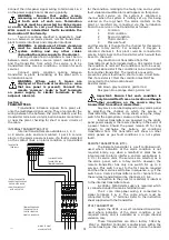
If a Contact Line fault (number 4) is indicated,
check that resistors are
tted in all unused conditions on
the internal transmitter, that the termination boards are
tted and the cabling between termination board and
transmitter is not short or open circuit.
If a Power Failure (number 2) is indicated, check
the 230Vac supply to the panel and the two fuses on the
power supply board.
When all panels are on, each condition in turn
should be created at the plant to con
rm the operation
and setting of the system. When it is not possible to
create a condition e.g. from a pressure switch on a
pipeline which is in use, disconnect the condition on the
plant side of the termination board to simulate condition
faults.
When satis
ed that all conditions operate
correctly, anti confusion tests must be
carried out by creating alarm conditions on
each service in turn and con
rming that
each panel on which the service is displayed
operates correctly.
Section 7
OPERATION
All that is required for routine operation is for
sta
to mute the audible alarm on alarm panels in their
areas as required, taking any action required by the
nature of the service fault. The audible will resound
periodically as long as the service fault remains,
requiring re-muting.
When a condition is to be at alarm condition for a
long time, the audible can be continuously muted as
follows. Open the panel and, while the alarm condition is
present, press the white push button on the rear of the
control board.
Note that any other conditions present at the
time will also be locked out. Close the panel and con
rm
that the condition has been successfully locked out by
pressing the test button. All other lamps should
ash,
the locked out condition(s) being steady. The lockout will
cancel as soon as the condition returns to normal.
NOTE. This operation should only be carried
out by service personnel.
TESTING
Periodically operate the test button and
ensure that all lamps illuminate and the audible
sounds. Periodically disconnect the mains sup ply
to each panel and ensure that the system fault
lamp
ashes and the audible sounds. Provided
that the battery in the panel under test is sound
and fully charged, no other panel will be a
ected
by this test. Any remote audible connected to the
alarm panel under test will sound.
6
<R C>
B
M
ON
1
2
3
4
3
<R C>
AUDIBLE SELECTOR SWITCH
CHANNEL SELECTOR SWITCH
LOCKOUT BUTTON
CENTRAL/REPEATER SELECTOR JUMPER
POWER FAILURE SELECTOR
JUMPER SHOWN SET FOR
SYSTEM FAILURE LAMP
ONLY
HINGE CLIP
ON
1 2
3 4
4
ON
1 2
3
4
2
ON
1 2
3
4
3
ON
1
2
3 4
1
ON
1 2
3
4
0
CONTROL
BOARD
B
M
SDXPIC2
VOLUME CONTROL
SHOWN AS CENTRAL


