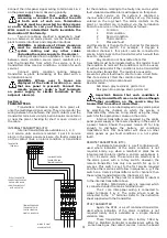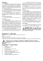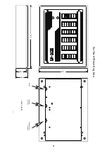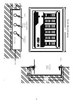
is design to be used WITHOUT termination boards.
Again the service channel is selected with a
rotary switch and the connection to the plant (or
manifold) is similar to the internal transmitter, only there
is no requirement for the Termination Board.
A 230Vac, 50/60 Hertz supply is required.
Note. This is the only item on the SDX-15
system which does not include a mains
termination cover. Note the warning label
on the outside of the box.
The 2 core inter-panel wiring is connected to
signal terminals 1 & 2. The cable screen must be
connected to and earth point or to the circuit earth.
COMPUTER INTERFACES.
Computer Interfaces are available which will give
volt-free contacts which are closed when a condition is
at normal. The relays are grouped in blocks of four,
giving four conditions plus normal, which is closed only
when all four conditions on that service are at normal.
The services are selected, as in the alarm panel, with a
rotary switch. However, the computer interface has only
one switch for up to 5 services. This switch is set to the
rst service required and the other services will follow in
sequence. e.g. if the switch on a 3 service interface is
set to channel 2 then the services detected will be
channels 2, 3,4 &5.
The computer interface is a self contained unit,
supplied as a 1, 2, 3, 4 or 5 service unit. A 230Vac, 50/60
Hertz supply is required, which is connected to terminals
under the mains terminal cover. The 2 core inter-panel
wiring is connected to signal terminals 1 & 2. The cable
screen must be connected to the ``S'' terminal.
The rating of the relay contacts is 0.5amp, 24V
dc resistive.
NOTE. Each SDX-15 central or repeater alarm
has an integral common alarm relay
tted as standard.
This relay opens when any alarm condition or fault
occurs on the panel and is similarly rated.
PLANT TO ALARM INTERFACE.
The plant to alarm interface is a low cost means
of complying with the C11 & HTM02-01 requirements for
indication of alarm status in plant or manifold room. It is
mounted in a clear fronted polycarbonate enclosure
protected to IP65, making it weatherproof and suitable
for use in VIE compound etc. with no further protection.
It consists of the following.
Four alarm conditions plus normal Power On &
system fault lamps. A one gas transmitter, connected to
the plant & set to the required channel in the same way
as a standard transmitter. Four relays, giving volt-free
contacts, closed under normal conditions, for connection
to other alarm systems, BMS systems etc. A battery
reserve to power the system failure lamp and the
transmitter in the event of power failure.
The plant to alarm interface requires a 230Vac,
50/60 Hertz supply and connection to the two core inter-
panel wiring.
Note. Being a basic indicator, the plant to alarm
interface has no audible alarm or test facility. Refer to
the instruction sheet supplied with the plant to alarm
interface for further details.
Section 5
SYSTEM DESIGN
If in doubt, please contact the
manufacturers. Errors can easily be recti
ed at
this stage.
The system must consist of a single central
panel, which should be mounted in a area which is
manned 24 hours a day. Select the number, location and
size (number of services to be displayed) of alarm panel
as required by C11/HTM02-01.
Select the location and size of transmitters. Use
internal transmitters if an alarm panel is in the same
room as the plant, or a remote transmitter if no
additional local indication is required.
Remember that a plant to alarm interface is
cheaper than a one service repeater with internal
transmitter for locations where local indication is
required.
With more than one service, a repeater with
transmitter is more economical. The distance between
the plant and the transmitter should be kept to a
minimum, and in any case should not exceed 100
metres.
See section 4 if conditions of a service are to be
transmitted from more than one location.
Transmitters are supplied with termination
boards, which must be mounted in or adjacent to the
plant.
Select Computer interfaces as required.
Section 6
SETTING UP
WARNING. STATIC SENSITIVE DEVICES.
OBSERVE HANDLING PRECAUTIONS.
Set the alarm panel at the central location as a
central by placing the jumper between the centre & right
hand pins on the central selector. Ensure that all other
panels have the jumper between centre & left hand pin.
Set the power failure mode as required using the
jumper adjacent to the ribbon cable connector. If the
any alarm panel is to have full battery operation under
power failure conditions, place the jumper between the
centre and lower pins on the power selector.
Allocate a channel for each service and enter the
name of the service on the log sheet in the “Gas
Service'' column. It may be useful to allocate the
services in the order in which they appear on the central
panel, although this is not necessary. Go to each
internal transmitter and set the rotary switch for each
service to the channel allocated to that service on the
log sheet. Set the rotary switch on each remote
transmitter to the channel allocated to the
rst service
on this transmitter. Set the channel for each computer
interface as for remote transmitters.
Set the rotary switch on each plant to alarm
interface to the appropriate channel. For each alarm
panel, set the rotary switch for each service displayed on
the panel to the channel allocated to that service.
If a column is not required e.g. if a spare service
has been installed for future use, set the rotary switch to
``F'' which switches o
that column.
Set the four audible switches for each service as
required (switch number 1 is condition 1, the
rst lamp
below normal. If a switch is on, the audible for that
condition will operate, otherwise it will never sound).
Mount the front plate & PCB onto the hinge by
springing the ends of the hinge apart &
tting into the
clips on the PCB.
Plug the ribbon cable on the power supply into
the control PCB. (it is keyed to prevent incorrect
connection).
Switch on the power to all panels, transmitters
etc. and connect the battery cables, observing polarity.
The system should now be operational.
No panels will operate if the central panel is not
functioning. In this case, all repeater panels will show an
Incoming Signal (number 1) on the system fault display
when the test button is pushed.
This will also happen if the inter-panel wiring is
reversed at any panel or the wiring is short circuited.
Disconnect each panel in turn until the fault
clears. If it does not, check for short circuits.
5


