


- 32 -
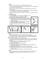
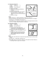
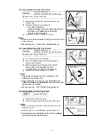
(6) Changing the Cooling Water
Change
Every 2,000 hours or 1 year
Cooling Water Total Capacity: Approximately 4 L
(Including the sub tank capacity of approx. 0.6 L)
1)
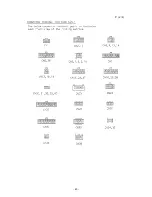
Open the top plate.
2)
Remove the radiator cap.
3)
Remove the water drain plug.
4)
Drain the cooling water and tighten the water drain plug.
5)
Change the cooling water in the sub tank.
6)
Pour cooling water into the water inlet until it reaches the mouth of the port.
7)
Tighten the radiator cap.
8)
Close the top plate.
<Note>
Replace the packing with a new part each time you change the cooling water.
Packing part no. : 6C090-58961 (Kubota part no.)
Operate the engine for a short period and check that there is no cooling water leakage.
Stop the engine when completed.
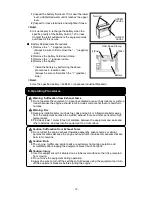
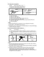
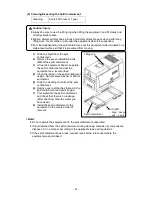
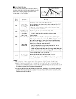
(7) Draining Liquid from the Spill Containment
Drain
Pre-operation
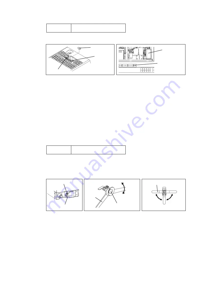
1)
Set a receptacle under the drain port of the spill containment to catch the liquid.
2)
Remove the plug (R 1/2") of the spill containment drain valve and turn the lever to
"OPEN".
3)
After draining the liquid, turn the lever to "CLOSE", and apply sealing agent to the
plug (R 1/2") or wrap it with sealing tape before tightening the plug.
<Note>
Secure the drain valve body using a spanner or similar tool so that it does not loosen
when removing/installing the plug by turning it.
It is possible that there is a fuel or oil leak if the drained fluid contains oily components.
If this occurs, check for leakage locations.
Although the fluids that can leak internally consist of oil, fuel, cooling water and
battery fluid, the spill containment does not have a function that can separate
rainwater that has leaked into the equipment from these internally leaked fluids.
Properly dispose of liquid drained from the spill containment in a manner according to
the applicable laws and regulations.
Fixing
Plug
Tighten
Loosen
Drain
Valve
Plug (R1/2
")
CLOSE
CLOSE
OPEN
Drain Valve Lever
Radiator Cap
Water Inlet
Top Plate
Sub Tank
Water Drain Plug
Summary of Contents for DGW400DMK
Page 2: ......
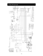
Page 41: ... 38 15 Engine Wiring Diagram ...
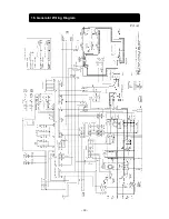
Page 42: ... 39 16 Generator Wiring Diagram P 1 2 ...
Page 43: ... 40 P 2 2 ...
Page 44: ... 41 MEMO ...
Page 45: ... 42 MEMO ...
Page 46: ... 43 MEMO ...
Page 47: ... 44 ...
Page 48: ... 45 2015 ...


