background image

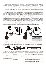
10.  For  electric  pumps  not  used  with  total  lift  (the  upper  and  lower  limits  of  lift  are 

specified),  they  must  be  used  within  the  usable  range  of  lift  to  avoid  damage  of  electric 
pumps  due  to  overload.  For  electric  pumps  used  with  total  lift,  the  pipe  diameter  adopted 
shall be consistent with but not greater than the specified pipe diameter to avoid overload.

11. Electric pumps are of dry structure, and it's not allowed to fill the cavity of motor with 

oil or water.

12. The oil chamber of the product is filled with No.10 white oil for food-level machinery 

to ensure that mechanical seal is lubricated and cooled effectively, and leakage may occur 
when  the  product  is  damaged  or  out  of  order.  In  such  service  environment  as  plantation, 
cultivation, or delivery and processing of drinking water or food, leaking white oil may cause 
damage  to  planted  plants  or  farmed  animals  or  pollute  drinking  water  or  food.  The  user 
shall  evaluate  the  service  environment  and  the  consequence  of  using  the  product  prior  to 
selection  and  use  of  the  product  to  confirm  whether  the  product  is  applicable,  and  shall 
invite  related  professionals  for  confirmation  where  necessary.  In  case  of  leakage  of  white 
oil, the user shall immediately stop using the product and handle it properly.

13. When electric pump is running, if it is needed to adjust the position of electric pump 

or touch the electric pump, the power must be disconnected first to avoid accidents.

Power must be 
disconnected 
when in touch 
with electric pump

ON
OFF

ON
OFF

ON
OFF

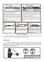
14. When electric pump is running, it's strictly prohibited to immerse cable joints or plug 

boards into the water; if this is needed for extension of cable, the joints shall be sealed and 
covered strictly to avoid electric leakage due to water seepage. (Refer to the figure below)

1 .   R e m o v e   t h e 
insulating  layer  without 
damaging conductor
2 .   S t a g g e r   s e v e r a l 
conductors in length
3.  Ensure  no  oil,  water 
or other dirt at the joint

No less than 10 times of conductor diameter

1.  Tighten  up  the  joint  by 
dividing  it  into  several 
strands  evenly  (at  least  6 
strands).
2. Cross two joints by such 
a  length  that  the  wire  ends 
reach the insulating layer at 
both ends.

1.  Tighten  up  the  strands  together,  take  out 
one  strand  from  the  middle  and  twine  it  to 
one  end  (the  twined  core  wire  contains  the 
other strands), and then twine other strands 
one by one.
2. Repeat the step above at the other end.
3.  Tighten  the  joint  with  pliers,  and  coat  the 
joint with tin to achieve the best effect. 
Note:  See  the  attached  figure  1  and 
attached figure 2 for other methods

Summary of Contents for DWE Series

Page 1: ...Models WQ D WQ D L1 WQ D L2 WQK WVSD DWE WQDS WQ D AS CB WQ QG WQ D 4P Vortex Type Micro Clean Water Pump SERVICE MANUAL SUBMERSIBLE ELECTRIC SEWAGE PUMP...

Page 2: ...Contents I Product Introduction II Operating Conditions III Structural Diagrams IV Installation Use and Matters Needing Attention V Maintenance VI Troubleshooting...

Page 3: ...ipal administration and environmental protection and pump liquids can contain ber scrap paper and other solid particles or soft solids e g muddy water grey water domestic sewage wastewater feces and u...

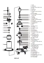
Page 4: ...Upper bearing block 17 Wave spring 18 Deep groove ball bearing 19 Stator core with winding 20 Enclosure 21 Rotor 22 Key 23 Deep groove ball bearing 24 O ring 25 Oil chamber 26 O ring 27 Slotted cheese...

Page 5: ...r 16 Key 17 Shoulder spring 18 Deep groove ball bearing 19 O ring 20 Oil chamber 21 Spring washer 22 Hexagon bolt 23 Deep groove ball bearing 24 Mechanical seal 25 Retainer ring for mechanical seal 26...

Page 6: ...acking washer 12 Wiring block 13 O ring 14 Cross recessed small pan head screw 15 Upper bearing block 16 O ring 17 Stator core with winding 18 Enclosure 19 Rotor 20 Key 21 Hexagon bolt 22 Oil chamber...

Page 7: ...O ring 16 Upper bearing block 17 O ring 18 Wave spring 19 Deep groove ball bearing 20 Enclosure 21 Stator core with winding 22 Rotor 23 Key 24 Deep groove ball bearing 25 O ring 26 Outlet joint 27 Rub...

Page 8: ...lt 20 Spring washer 21 Deep groove ball bearing 22 O ring 23 Oil chamber 24 Hexagon socket head cap screw 25 O ring 26 Slotted cheese head screw 27 Deep groove ball bearing 28 Mechanical seal single e...

Page 9: ...y 19 Hexagon bolt 20 Spring washer 21 Deep groove ball bearing 22 O ring 23 Oil chamber 24 Hexagon socket head cap screw 25 O ring 26 Slotted cheese head screw 27 Deep groove ball bearing 28 Mechanica...

Page 10: ...d small pan head screw 15 Deep groove ball bearing 16 Stator core with winding 17 Enclosure 18 Rotor 19 Flat key 20 O ring 21 O ring 22 Cross recessed small pan head screw 23 Spring washer 24 Bearing...

Page 11: ...er 17 Closed wiring terminal 18 Upper bearing block 19 O ring 20 O ring 21 Insulation paper 22 Wave spring 23 Deep groove ball bearing 24 Stator core with winding 25 Nameplate 26 Double end stud 27 En...

Page 12: ...full thread 17 Spring washer 18 O ring 19 Slotted cheese head screw 20 Mechanical seal 21 O ring 22 Oil chamber cover 23 Framework oil seal 24 Flat washer 25 Impeller 26 Spring washer 27 I type hexago...

Page 13: ...sed small pan head screw 16 O ring 17 Deep groove ball bearing 18 Stator core with winding 19 Enclosure 20 Rotor 21 Flat key 22 O ring 23 O ring 24 Circlip for shaft 25 Deep groove ball bearing 26 Dee...

Page 14: ...ng 13 Enclosure 14 Mechanical seal 15 Deep groove ball bearing 16 Oil chamber 17 Oil chamber cover 18 Framework oil seal 19 Impeller 20 O ring 21 Pump casing 22 Air vent screw 23 Cap nut 24 Spring was...

Page 15: ...r bearing block 11 Stator core with winding 12 Enclosure 13 Oil chamber 14 O ring 15 Slotted cheese head screw 16 Hexagon bolt full thread 17 Mechanical seal 18 Oil chamber cover 19 Hexagon socket hea...

Page 16: ...pper bearing block 18 Bearing 19 Stator core with winding 20 Enclosure 21 Hexagon bolt full thread 22 Spring washer 23 Split washer 24 Rotor 25 Key 26 Shoulder ring 27 Circlip for hole 28 Bearing 29 C...

Page 17: ...bolt full thread 16 Spring washer 17 Rotor 18 Key 19 Circlip for hole 20 Bearing 21 Circlip for shaft 22 O ring 23 Oil chamber 24 Spring washer 25 Hexagon socket head cap screw 26 Mechanical seal 27 R...

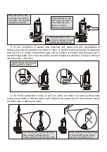
Page 18: ...led with electrical leakage protector and a yellow green wire attached with earthing mark in the outgoing cable of electric pump shall be earthed reliably For electric pumps provided with plug at deli...

Page 19: ...clamp steel delivery pipe can be reliably connected with screwed joint or welded ange plate and a rope should be reeved through the handle or lift ring for lifting of electric pump in the water Tighte...

Page 20: ...h is no more than 5m Electric pump shall not be out of water surface Electric pump shall not be immersed in mud to prevent impeller from being blocked or jammed by water plants 9 For single phase elec...

Page 21: ...white oil the user shall immediately stop using the product and handle it properly 13 When electric pump is running if it is needed to adjust the position of electric pump or touch the electric pump t...

Page 22: ...layer by about 10mm 2 Wrap the joint with plastic insulating tape for three layers with the posterior layer exceeding the two ends of the previous layer by about 10mm Figure 1 Figure 2 Figure 3 It s...

Page 23: ...used oil with No 10 white oil for food level machinery to reach 95 volume of chamber 3 If electric pump is not used for a long time it should not be immersed in the water electric pump shall be place...

Page 24: ...ed 3 Stator winding is burnt out 1 Check whether the lift used or supply voltage meets requirements and adjust it 2 Clear away foreign matters 3 Insert winding again for overhaul Stator winding is bur...

Reviews: