4-7
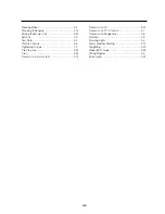
Air Cleaner
………………………………………
3-10
Alternator
…………………………………………
3-19
Audible Backup Alram
…………………………
2-23
Armrest
……………………………………………
2-1
Battery
……………………………………………
3-22
Bleeding the Fuel System
………………………
3-9
Brake Controls
…………………………………
2-6
Brake Pedals
……………………………………
2-6
Break-in Procedures
……………………………
2-11
Canopy
……………………………………………
2-22
Cast Iron Weights
………………………………
2-20
Cellular Phone Socket
…………………………
2-21
Cold Weather Starting
…………………………
2-13
Contents
…………………………………………
0-1
Controls and Instruments
………………………
2-1
Cooling System
…………………………………
3-16
Diesel Fuel
………………………………………
3-3
Differential Control
………………………………
2-17
Driving the Mower
………………………………
0-3,
2-20
Dual Pedal Turning Brake Kit
……………………
2-23
Engine
……………………………………………
3-7
Engine Oil
…………………………………………
3-7
Engine, Starting
…………………………………
2-12
Engine, Stopping
…………………………………
2-14
Fan Belt
…………………………………………
3-18
Final Reduction Gear Case
……………………
3-15
Foot Pedal, H.S.T
………………………………
2-7
Front Axle differential Case
……………………
3-12
Fuel Filter
…………………………………………
3-8
Fuel Shutoff Valve
………………………………
3-8
Fuse Block
………………………………………
3-20
Fusible Link
………………………………………
3-20
General Information
……………………………
1-1
General Maintenance
……………………………
3-16
Hardware Torque Charts
………………………
1-2
Head Lamp
………………………………………
3-21
Head Light Switch
………………………………
2-5
Hood Latch
………………………………………
3-6
Hydraulic Lift Control
……………………………
2-10
Hydraulic Lift System
……………………………
2-18
Hydraulic System Oil
……………………………
3-12
Hydraulic System Oil filter
………………………
3-14
Hydrostatic Transmission
………………………
2-15
Identification Plate
………………………………
1-1
Instruction Decals
………………………………
0-7
Instruments and Controls
………………………
2-1
Instrument Lights
………………………………
3-21
Instrument Panel
…………………………………
2-4
International Symbols
……………………………
1-3
Key Switch
………………………………………
2-5
Lift Control
………………………………………
2-10
Lighting
……………………………………………
2-5
Lubrication
………………………………………
3-3
Lubrication Fittings
………………………………
3-3
Lubrication and Maintenance
…………………
3-1
Lubrication and Maintenance Chart
……………
3-2
Maintenance and Lubrication
…………………
3-1
Maintenance and Lubrication Chart
……………
3-2
Maintenance and Storage
………………………
0-4
Mower Hydraulics
………………………………
2-15
Oil
Engine
…………………………………………
3-7
Final Reduction Gear Case
…………………
3-15
Front Axle Differential Case
…………………
3-12
Hydraulic System
……………………………
3-12
Power Steering
………………………………
3-12
Rear Axle
………………………………………
3-15
Transmission
…………………………………
3-12
Oil filter, Hydraulic System
………………………
3-14
Operation
…………………………………………
0-3,
2-1
Operating the Mower
……………………………
0-3
Operation of the PTO
……………………………
2-16
Overheat Alarm Buzzer
…………………………
2-21
Parking Brake Control
…………………………
2-6
Predelivery Service
………………………………
4-11
Preparation
………………………………………
0-2
PTO Control Lever
………………………………
2-9
PTO, Operation
…………………………………
2-16
Range Lever, H.S.T
……………………………
2-8
Rear Axle
…………………………………………
3-15
Reclining Lever
…………………………………
2-1
Recommened Lubricants
………………………
3-3
Refueling the Mower
……………………………
3-5
ROPS
……………………………………………
2-2,
3-23
Safety
……………………………………………
0-2
Safety Decals
……………………………………
0-5
Safety Frame (ROPS)
……………………………
2-2
Seat
………………………………………………
2-1
Seat Belt
…………………………………………
2-1
Seat Belt Anchor
…………………………………
2-21
Seat Lifting
………………………………………
3-12
Service ACCES
…………………………………
3-6
Side PTO
…………………………………………
2-22
Sound Measurements
…………………………
4-5
Specifications
……………………………………
4-1
Speed Control, H.S.T
……………………………
2-7
Starting the Engine
………………………………
2-12
INDEX
Summary of Contents for CM314
Page 1: ...TRACTOR OPERATOR S MANUAL MODEL CM314 CM374 I H I GROUP IHI Shibaura Machinery Corporation...
Page 68: ...4 6 Wiring Diagram...
Page 73: ...4 13...
Page 74: ...4 14...


