


824-033
15
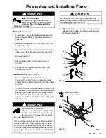
Removing and Installing Pump
WARNING
INJECTION HAZARD
To reduce the risk of serious injury,
whenever you are instructed to relieve
pressure, follow the Pressure Relief
Procedure on page 7.
Removal
See Fig. 12.
1.
Flush pump, if possible. Relieve pressure again.
Stop pump with piston rod in lowest position, if
possible.
2.
Disconnect drain tube (101) from pump (39) and
suction tube (42).
3.
Remove suction tube (42); hold wrench on pump
intake valve (223) to keep pump from loosening.
4.
Remove hose (47).
5.
Push retaining spring (35) up and push out
pin (20).
6.
Loosen locknut (38) and unscrew pump from
bearing housing (27).
Installation
See Fig. 12 and 13.
1.
Screw displacement pump into bearing
housing (27) until pin hole in connecting rod as-
sembly (29) and displacement rod (A) align. Install
pin (20).
2.
Continue to screw pump into bearing housing until
top threads of pump cylinder are flush with face of
bearing housing and outlet nipple (75) is straight
back. Push retaining spring (35) into groove
around connecting rod. Tighten locknut (38) to 70
ft-lb (95 N.m).
WARNING
MOVING PARTS HAZARD
Be sure the retaining spring (35) is firmly
in the groove of the connecting rod, all
the way around, to prevent it from work-
ing loose due to vibration.
If the pin works loose, it or other parts could break
off due to the force of the pumping action. These
parts could be projected through the air and result
in serious bodily injury or property damage, includ-
ing damage to the pump, connecting rod or bearing
housing.
CAUTION
If the locknut (38) loosens during operation, the
threads of the bearing housing (27) will be damaged.
Be sure to tighten the locknut firmly.
3.
Tighten packing nut/ wet-cup just enough to stop
leakage, but no tighter. Fill wet–cup/packing nut
1/3 full with Graco TSL.
7392A
27
Fig. 12
42
223
47
35
20
101
A
39
38
07393A
Fig. 13
1
29
35
27
38
Face of bearing housing
1
75
2
Torque to 70 ft–lb (95 N.m)
2
20
Summary of Contents for ULTIMATE 824-030
Page 27: ...Notes...


