background image

LVP919 SERIES USER MANUAL

Chapter 4 Description for Front Panel Buttons

12

Chapter 4 Description for front panel buttons

1

. Sketch map of front panel buttons

1

2

3

3

3

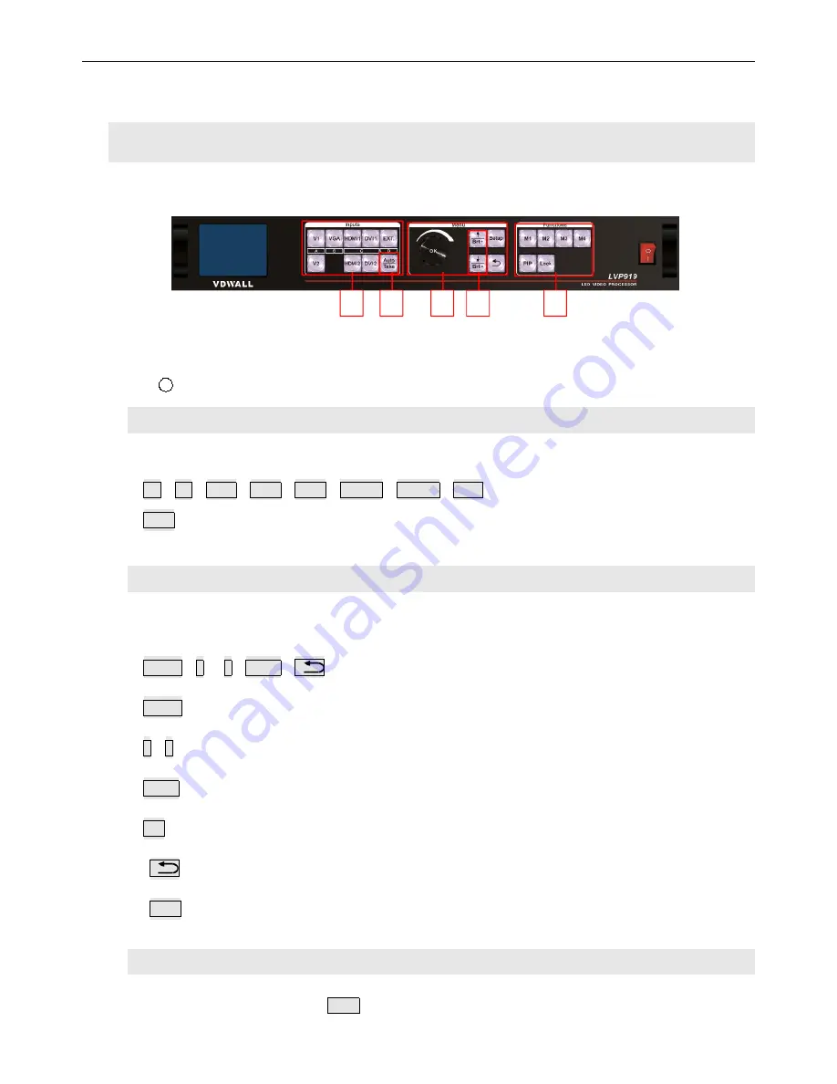
Pic 4-1 Sketch map of front panel buttons

1

Selection buttons of input signals

② Setup buttons

③ Other function buttons

1

. Selection buttons of input signals

Selection buttons of input signals are used for selecting input signals.

V1

V2

VGA

DVI1

DVI2

HDMI1

HDMI2

EXT.

Take

switch from current signal to the pre-select signal under

Pre.+Take switching

mode.

2

. Setup buttons

Setup buttons

set images output parameters

Setup

Knob

Setup

Enter the setup menu

Select setup options

Knob

Knob this button to adjust values or parameters

OK

Press this button to save parameters

Return to the previous item

Auto

Can be used to switch the current outputs while it is on outputs parameter menu.

3

.

VGA auto-adjustment buttons

VGA auto-adjustment buttons (

Auto

): Adjust VGA input signals automatically.

Summary of Contents for LVP919 Series

Page 1: ...oom B 5th Floor Bldg C Tongfang Information Harbor Nashan Hi Tech Park Nanshan District Shenzhen Tel 86 755 2675 0210 2650 1506 2663 6668 Marketing QQ 400 0660 628 Technical QQ Group 422024594 LVP919 Series LED VIDEO WALL PROCESSOR USER MANUAL V1 0 ...

Page 2: ...LVP919 SERIES USER MANUAL Contents 2 Contents ...

Page 3: ...efore using this device and keep it well for future use 2 Please pull the power plug out of receptacle while lighting or you are not going to use the device for a long time 3 Nobody other than professional technicians can operate the device unless they have been appropriately trained or under guidance of technicians 4 Please do not fill in anything in the vent of the device in order to prevent equ...

Page 4: ...ything is missing please contact the dealer Standard accessories The accessories supplied with this LED Video Processor may differ from the figures on the User s Manual but they are applicable for the regions where you live LED sending card is optional 1 5m power cord 1 1 5m DVI cable 1 0 5m DVI cable 4 1 5m USB cable 1 Operation CD 1 User manual 1 BNC RCA adapter 2 PCB audio adapter 2 ...

Page 5: ... Communication port Audio port 2 Ports description 1 Inputs LVP909 supports 8 video input signals as follows Ports Description V1 V2 2 channels of Composite video input PAL NTSC VGA 1 channel of PC analog signal input DVI1 DVI2 2 channels of DVI digital inputs compatible with HDMI 1 3 inputs HDMI1 HDMI2 2 channels of HDMI digital inputs HDMI 1 3 EXT 1 channel of extended input SDI HD SDI 3G SDI is...

Page 6: ...D sending cards or monitors 3 Communication ports Ports Description LAN TCP IP local area network control interface USB USB Communication port RS232 In Serial communication interface connected to PC through RS232 port to realize PC software control RS232 Out Serial communication output cascading RS232 LEV it can control several processors by only one PC ...

Page 7: ...LVP919 SERIES USER MANUAL Chapter 3 Hardware Connection 7 3 Hardware connection diagram Pic 3 3a LVP919 Hardware connection diagram ...

Page 8: ... G B 0 7 V p_p 75Ω DVI Format PC VESA Standard 1920 1200_60Hz HDMI1 3 CEA 861 1080p_60Hz HDMI Format PC VESA Standard 1920 1200_60Hz HDMI1 3 CEA 861 1080p_60Hz SDI Format SMPTE259M C SMPTE 292M SMPTE 274M 296M SMPTE 424M 425M 480i_60Hz 576i_50Hz 720p 1080i 1080p Input Interface CVBS BNC VGA 15pin D_Sub Female DVI 24 1 DVI_D HDMI Type A HDMI port SDI BNC 75Ω Type Quantity of Audio Outputs Analogous...

Page 9: ..._D Type Quantity of Audio Outputs Analogous Dual Audio Channel x1 Load Impedance of Audio Outputs 70mW 32Ω or 105mW 16Ω Others Control Port RS232 USB LAN Voltage of Input 100 240VAC 50 60Hz Power Consumption 35W Temperature of Environment 0 45 Humidity of Environment 15 85 Size of Product 482 6 L x274 W x66 6 H mm Packing Size 535 L x400 W x145 H mm Weight G W 5 6Kg N W 3 7Kg ...

Page 10: ...LVP919 SERIES USER MANUAL Chapter 3 Hardware Connection 10 Product Dimensions Pic 3 4a LVP919 Product Dimensions ...

Page 11: ...LVP919 SERIES USER MANUAL Chapter 3 Hardware Connection 11 RS232 cable order Pic 3 4b RS232 converted to RJ45 cable order ...

Page 12: ...electing input signals V1 V2 VGA DVI1 DVI2 HDMI1 HDMI2 EXT Take switch from current signal to the pre select signal under Pre Take switching mode 2 Setup buttons Setup buttons set images output parameters Setup Knob Setup Enter the setup menu Select setup options Knob Knob this button to adjust values or parameters OK Press this button to save parameters Return to the previous item Auto Can be use...

Page 13: ... Mode when PIP is on 6 Splice mode buttons Splice mode buttons M1 M2 M3 M4 call and set the display modes call splice modes call PIP modes on PIP menu 7 Lock button Lock button Lock lock all buttons When lock is on The red light will be on all the time The other buttons are not available the Lock button Press Lock button for 3 times without stop to unlock this function the red light is off 8 Infor...

Page 14: ...Pre Take switch which can be set in user setup menu 3 1 switch mode One key switch is the default switching mode Switch to a new signal by pressing input signals selection buttons Pre Take switch adopts to press input signal buttons to preselect and then press TAKE button to switch from current input signal to preselect signal The input signals selection buttons are as the follow form Buttons Desc...

Page 15: ...cting the input signal such as HDMI LCD shows the status of the current selected input signal source on the second row if there is no input signal source it will show No effective inputs and the indicator flash at the same time If there do exist an effective input signal then it will show the input format such as 1080p_60Hz 2 Pre Take LCD screen shows as following pictures Curr Input HDMI1 Curr In...

Page 16: ...ups of input signals unless they belong to the same group For example if the current input signal is V1 V1 belongs to Group A you can only choose one input signal from Group B Group C or Group D the groups are as follows A B C D V1 V2 VGA DVI1 DVI2 HDMI1 HDMI2 EXT 3 Switching time selection We can realize seamless switching among the 4 groups of input signals unless they belong to the same group T...

Page 17: ...LCD screen will show you what the main input signal and PIP input signal is and the position and size of the corresponding image As follows Main Input HDMI1 Main In Status 1080p_60Hz PIP Input V1 PIP In Status PAL Main Pos Size 0 0 1920 540 PIP Pos Size 0 540 1920 540 PIP Mode M1 Pic 5 2a LCD display interface Change the PIP input press the corresponding button to select a input signal and this se...

Page 18: ...tness the lowest is 0 BRT To increase output brightness the highest is 32 2 VGA input auto adjustment Auto When LVP919 is under one key directly switching mode the current input source is a valid VGA input signal press Auto to enable the LVP919 to automatically adjust the sampling parameters of the VGA input signal making the VGA image clear and complete This operation is usually performed only wh...

Page 19: ...n order Input HDMI1 In Status 1080p_60Hz Out1 Out Pos Size 0 0 1920 1080 Out1 In Pos Size 0 0 1920 1080 Switch Mode One Key SW Pic 5 4a LCD display interface In the signal switching state press OK to display the current settings and information of LVP919 System Info Model Lvp919 Version V0 0 8 IP 192 168 1 8 Mask 255 255 255 0 Gate 192 168 1 1 Mac 76 64 77 00 00 00 Resolution 1920x1080_60Hz Pic 5 ...

Page 20: ...9 SERIES USER MANUAL Chapter 5 Instructions of Basic Operations For Users 20 System Info Input V0 0 8 Output V0 0 8 Pic 5 4c LCD display interface System Info Made Data 2018 07 Pic 5 4d LCD display interface ...

Page 21: ...brightness etc communication language audio and advance Setup 1 Output Image 2 PIP 3 Input Video Signal 4 Color Brightness etc 5 Communication 6 语言 Language 7 Audio 8 Advance Pic 6 LCD display interface After the system start press Setup to enter user setup menu Press buttons to select corresponding setting items Then press knob button OK to enter and press to return to the previous menu Here we w...

Page 22: ...tput image mosaic 1 Output Image 1 1 Resolution 1920x1080_60Hz 1 2 Fast Mosaic1 1 3 Fast Mosaic2 1 4 Manual Mosaic Pic 6 1a LCD display interface 1 Change the output resolution Operation method Press or button to select 1 1 resolution Turn the knob button to select the right parameter Press OK button The confirmation menu appears as below Press OK button again to restart the device The changed par...

Page 23: ...aic1 M2 1 2 1 Mosaic Mode 2x1 1 2 2 Out1Hori Width 1920 1 2 3 Out2Hori Width 1920 1 2 4 Vert Height 1080 1 2 5 Auto Calculation OK To Apply Pic 6 1c LCD display interface Fast Mosaic 1 operation method 1 Firstly confirm that the LED screens have the same point spacing and arranged according to the rules of x row x column and then select the corresponding mosaic mode such as 1x2 2 Press the display...

Page 24: ...ative to the total mosaic screen 1 3 4 Unit Height 1 3 5 Unit H_Start 1 3 6 Unit V_Start 1 3 7 Auto Calculation Apply automatic mosaic parameters Fast Mosaic2 Operation method 1 Firstly press display mode button M1 M2 M3 M4 to select required setting mode 2 Press Auto switching to the required to adjust output port Out1 Out4 3 Set the total width and height of the entire LED screen that need to mo...

Page 25: ...ay interface Adjustment items Description 1 4 1 In Width The DVI input image position and size of the output port captured 1 4 2 In Height 1 4 3 In H_Start 1 4 4 In V_Start 1 4 5 Out Width Processor output parameters 1 4 6 Out Height 1 4 7 Out H_Start 1 4 8 Out V_Start Manual Mosaic operation method 1 Firstly press display mode button M1 M2 M3 M4 to select required setting mode 2 Press Auto switch...

Page 26: ...and sub image position and size of PIP and output image mosaic 2 PIP M4 PIP M1 2 1 PIP Width 960 2 2 PIP Height 1080 2 3 PIP H_Start 960 2 4 PIP V_Start 0 2 5 Main Width 960 2 6 Main Height 1080 2 7 Main H_Start 0 2 8 Main V_Start 0 Pic 6 2 LCD display interface Operation method Press PIP to switch current PIP mode then press or to select the setting options rotate knob to adjust the parameters th...

Page 27: ...witching mode and switching time Switching mode can be set to One Key SW or Pre Take SW The switching time can be set to 0 second seamless switching and 0 5 second 1 second 1 5 second fade in and out switching 3 Input Video Signal 3 1 Switch Mode One Key SW 3 2 Switch Time 0 Sec Pic 6 3 LCD display interface Operation method press or to select the setting options rotate knob button OK button to ad...

Page 28: ... 4 1 Brightness 50 50 4 2 Contrast 50 50 4 3 Color 50 50 Pic 6 4 LCD display interface Adjustment items Description 4 1 Brightness Adjustment range 0 100 default 50 4 2 Contrast Adjustment range 0 100 default 50 4 3 Color Adjustment range 0 100 default 50 Note 1 To make sure of full gray scale of output image they are always set as default value 2 Color parameters are only available for V1 V2 SDI ...

Page 29: ...IP address subnet mask gate and MAC address It can also number multiple LVP919 to achieve multi machine cascade through RS232 5 Communication 5 1 IP 192 168 1 8 5 2 Mask 255 255 255 0 5 3 Gate 192 168 1 1 5 4 Mac 76 64 77 00 00 00 5 5 Device ID 1 Pic 6 5 LCD display interface Operation method In 5 Communication press or to select the setting options rotate knob button OK button to adjust the param...

Page 30: ...User Setup Menu Instructions 30 6 Language setting LVP919 supports Chinese and English language Rotate Knob button OK button to select one and press OK to save and effect 6 语言 Language 6 1 语言 Language English Pic 6 5 LCD display interface ...

Page 31: ...g audio input of any input of all video inputs respectively and switch synchronously with the switching of the video input signal 7 Audio 7 1 AD1 Config V1 7 2 AD2 Config V2 7 3 AD3 Config VGA Pic 6 7 LCD display interface Operation method button to select the corresponding audio configuration menu turn the knob to change the input signal configured by the audio port press OK to save If SDI and HD...

Page 32: ...USER MANUAL Chapter 6 User Setup Menu Instructions 32 8 Advanced setting 8 Advance 8 1 Adc Calibration OK To Apply 8 2 EXT Input Mode SDI 8 3 DVI Hotplug On 8 4 Device Reset OK To Apply Pic 6 8a LCD display interface ...

Page 33: ...ork normally Operation method Enter 8 2 EXT Input Mode option rotate the knob to select the relative module option and press OK button to save After the processor restart the setting will come into effect 3 DVI Hotplug The DVI hot plug signal is sent by the processor to a signal source system such as graphics card and is used as a basis for whether the signal source sends a DVI signal to the proce...

Page 34: ...LVP919 SERIES USER MANUAL Chapter 6 User Setup Menu Instructions 34 Tips Data will reset Press OK to reset Press return to cancel Pic 6 8b LCD display interface ...

Page 35: ...LVP919 SERIES USER MANUAL Chapter 7 Module Description 35 Chapter 7 Module description LVP919 No extended module not support SDI Input LVP919S have SDI extended module support SDI input ...

Page 36: ...LVP919 SERIES USER MANUAL Appendix correction log table 36 Appendix correction log table Version Date Description Draft 1 0 2018 6 12 LVP919 first release Lts ...

Reviews: