background image


Shenzhen Chainway ITS Co., Ltd 

23 

18 

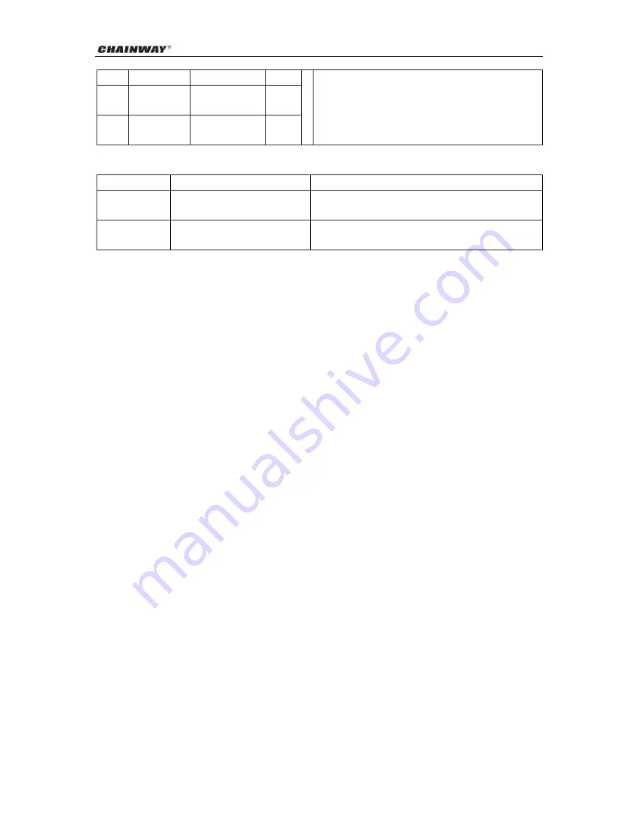
Input port 4   

High-beam light 

Pink   

19 

Input port 5   

ACC 

testing 

line/right turning   

Blue   

20 

Ground   

Signal  grounding 

(cut oil/power)   

Black   

Description of indicators:   

Red indicator 

GPRS/CDMA1X work indicator 


Green indicator   

Network connection indicator   

Long flickering is for data network and short flickering is for 

message network   

Yellow indicator   

GPS positioning indicator   

Long flickering is for valid positioning and short flickering is 

for invalid positioning   

4 Guide to Installation and Maintenance 

The  installation  of  the  terminal  of  CWS-8004  Automobile  Driving  Recorder  shall  be  performed  by 

authorized personnel of our company or professional technical personnel of any of our local service centers. 

The  user  shall  not  dismantle  or  repair  it  without  authorization.  Otherwise  we  assume  no  liability  for  any 

consequence arising out of this. 

4.1 The Procedure for Installation 

1. 

Fix the display screen on the place convenient for viewing by the driver and fix the terminal in a cool 

and  well-ventilated  place,  a  bit  far  from  the  car-borne  acoustic  device  to  prevent  from  any  signal 

interference. Make sure the LCD surface on the upper side of the screen shall be prevented from any 

direct sunshine. Otherwise, service life of the screen will be shortened. 

2. 

Install the terminal in a hidden  place  of the  vehicle and  fix it with a screw. (Do  not select a place  of 

high temperature or near the air conditioner, for high temperature will easily shorten service life of the 

device.  And  if  it  is  too  near  from  the  air  conditioner,  condensed  water  from  the  air  conditioner  will 

easily enter the terminal and result in short circuit and burning of the device). 

3. 

Keep electricity quantity in the automobile battery sufficient and the  work  normal.  Power supply  for 

the device is DC9V~32V. Prior to installation, confirm if the power supply system of the user is within 

this  range,  for  exceeding  the  maximum  voltage  of  the  terminal  will  result  in  the  damage  of  the 

terminal. Prior to cable connection, total power source of the vehicle shall be turned off (in the state of 

power  off),  and  the  cable  shall  be  prevented  from  being  cut  through,  pressed,  treaded  and  the 

connector shall be kept clean and locked. 

4.2 Maintenance and Servicing 

The  following  proposals  help  you  abide  by  the  warranty  repair  provision,  and  ensure  the  terminal  of  CW-GPS701 

Automobile Driving Recorder to work more stably and reliably. 

Summary of Contents for CW-GPS701

Page 1: ...GPS Automobile Driving Recorder Model CW GPS701 User Manual...

Page 2: ...roduct CWS 8004 Automobile Driving Recorder 10 3 2 LCD after Starting Device 10 3 2 1 LCD Logon Page 10 3 2 2 LCD functional keys 10 3 3 LCD Main Menu 11 3 3 1 Speed in the latest 15 minutes 11 3 3 2...

Page 3: ...3 5 1 Login system 20 3 5 2 Read vehicle data 20 3 6 Connection between the Printer and the Terminal 21 3 7 Access Recorder Data via USB Interface 21 3 8 Interfaces and Connection Cables 21 4 Guide to...

Page 4: ...vehicle number vehicle type driver ID driving license number USB port can copy data stored in CW 701 RS485 RS232 Can Bus Support fuel level sensor only for customers have own software Support Camera C...

Page 5: ...hes and reference for public security and traffic police authorities for handling accidents and breaking cases It can provide more comprehensive reference data for vehicle inspection e g annual inspec...

Page 6: ...s of the Product CW GPS701 Automobile Driving Recorder including 1 Terminal of CW GPS701 Automobile Driving Recorder 2 Power line GPS GSM antenna internal battery 3 Installation Leg Velcro Installatio...

Page 7: ...10 Functions of driving recorder 11 Compression and back transmission 12 Status query Detailed Description of Functions The functions of driving recorder are contained inside The driving recorder insi...

Page 8: ...data Intelligent power reduction At the speed of 2km h the terminal goes on transmitting back 10 times of location information normally and then the terminal enters a hibernation mode and the interva...

Page 9: ...out of the danger Power failure alarm Power for the car borne device is supplied by the storage battery in the vehicle In case of power failure it will give out power failure alarm signals to the mon...

Page 10: ...cket 3 2 LCD after Starting Device 3 2 1 LCD Logon Page Turn on the power start the device and wait for initialization of the device to complete You can see GSM satellite signal ACC status date time G...

Page 11: ...he record of average speed per minute in the latest 15 minutes will be shown on the display screen and upward and downward keys can be used for viewing Diagram After viewing press F4 to return and exi...

Page 12: ...it will appear If the printing operation fails the words of Printing failed will appear After printing is completed press return key to return to the default display interface Diagram Press printing k...

Page 13: ...ss OK key to select Vehicle RPM Or press F1 key directly to enter Figure Record of vehicle round will be shown on the display screen Figure After viewing press Return key to return and exit the interf...

Page 14: ...Description of functions The driver inserts the IC card after getting on to show driver information and record driving time If the driver is required to be replaced press OK key to select Driver Logou...

Page 15: ...ter viewing press Return key to return to the previous interface k System status Figure Select System status and press OK key to enter the page of system status and current system status information w...

Page 16: ...igure Select Set Parameter enter password 333666999 and press OK to enter parameter setting page Use of keys changed 0 9 At the bottom of LCD Choose input content Text Message System State Set Paramet...

Page 17: ...Figure After adjustment press OK key to return to the previous menu 3 4 2 Center IP Figure Select Center IP and press OK key to confirm Figure APN UserName APN Password Write IC data Time Zone Show Ve...

Page 18: ...inistrators and they will not be introduced here 3 4 4 Set APN Figure Select Set APN and press OK to confirm 3 4 5 Transmit Interval Description of functions Set data transmit interval for terminal Te...

Page 19: ...N do not need user name password In this case don t set the parameter Page 2 3 4 8 APN Password Description of functions Set APN s password Page 2 Terminal ID Center IP Center Port Set APN Center Numb...

Page 20: ...ense length 18 3 5 Read 701 data by software 3 5 1 Login system 1 Login our system http 218 201 94 112 gps with user name demo password demo 2 Use E map part driving recorder function only supported b...

Page 21: ...f the printer before printing refer to guide for use of printer for relevant parts 3 7 Access Recorder Data via USB Interface Insert a flash disk into the USB interface and operate in accordance with...

Page 22: ...larm speaker dipped Beam Brown 7 CANBUS1_CABL USB data2 Black 8 Output port 1 Power cut off 8 USB_D 1_HOST Debugging serial port Grey 9 Output port 2 Oil cut off control Purple 9 Input port 1 Fog ligh...

Page 23: ...signal interference Make sure the LCD surface on the upper side of the screen shall be prevented from any direct sunshine Otherwise service life of the screen will be shortened 2 Install the terminal...

Page 24: ...g vehicle guard products from the manufacturer and their authorized distributors 2 The consumers enjoy a warranty repair period of 12 months free of charge from the date they purchase the product With...

Page 25: ...o the authorized distributor or the authorized service center for maintenance or replacement The relevant charge for dismantling the product is not covered in the provision for limited warranty repair...

Reviews: