


Important
Information
IMPORTANT
Before using the projector, please read this operation manual carefully.
OPERATION MANUAL
ENGLISH
Model No.: XV-Z90E
Serial No.:
ENGLISH
WARNING:
WARNING:
CAUTION:
WARNING:
OFF
Downloaded From projector-manual.com Sharp Manuals
Important
Information
IMPORTANT SAFEGUARDS
ATTENTION: Please read all of these instructions before you operate your Projector for
the first time. Save these instructions for future reference.
For your own protection and prolonged operation of your Projector, be sure to read the following IMPORTANT
SAFEGUARDS carefully, before use.
This projector has been engineered and manufactured to ensure your personal safety. But IMPROPER USE CAN
RESULT IN POTENTIAL ELECTRICAL SHOCK OR FIRE HAZARDS. In order not to defeat the safeguards
incorporated into this Projector, observe the following basic rules for its installation, use and servicing.
17. Unplug the Projector equipment from the wall outlet and
refer servicing to qualified service personnel under the
following conditions:
a. When the power cord or plug is damaged or frayed.
b. If liquid has been spilled into the Projector.
c. If the Projector has been exposed to rain or water.
d. If the Projector does not operate normally when
you follow the operating instructions. Adjust only
those controls that are covered by the operating
instructions, as improper adjustment of other
controls may cause damage and will often require
extensive work by a qualified technician to restore
the Projector to normal operation.
e. If the Projector has been dropped or the cabinet
has been damaged.
f.
When the Projector exhibits a distinct change in
performance
this indicates a need for service.
18. When replacement parts are required, be sure the ser-
vice technician has used replacement parts specified by
the manufacturer that have the same characteristics as
the original parts. Unauthorised substitutions may result
in fire, electric shock, or other hazards.
19. This Projector is provided with one of the following types
of plugs. If the plug should fail to fit into the power outlet,
please contact your electrician.
Do not defeat the safety purpose of the plug.
a. Two-wire type mains plug.
b. Three-wire grounding type mains plug with a
grounding terminal.
This plug will only fit into a grounding type power
outlet.
1. Unplug the Projector from the wall outlet before cleaning.
2. Do not use liquid cleaners or aerosol cleaners. Use a
damp cloth for cleaning.
3. Do not use attachments not recommended by the
Projector manufacturer, as they may cause hazards.
4. Do not use the Projector near water; for example, near a
bathtub, washbowl, kitchen sink, laundry tub, in a wet
basement, near a swimming pool, etc. Never spill liquid
into the projector.
5. Do not place the Projector on an unstable cart, stand, or
table. The Projector may fall, which may cause serious
injury to a child or an adult, and/or serious damage to the
unit.
6. Wall or Ceiling Mounting
The product should be
mounted to a wall or ceiling only as recommended by
the manufacturer.
7. Projector equipment and cart
combinations should be moved
with care. Quick stops, excessive
force, and uneven surfaces may
cause the equipment and cart
combination to overturn.
8. Slots and openings in the cabinet back and bottom are
provided for ventilation. To ensure reliable operation of
the Projector and to protect it from overheating, these
openings must not be blocked or covered. The openings
should never be covered with cloth or other material.
9. This Projector should never be placed near or over a
radiator or heating vent. The Projector should not be
placed in a built-in installation such as a bookcase unless
proper ventilation is provided.
10. The Projector should be operated only from the type of
power source indicated on the back of the projector or in
the specifications. If you are not sure of the type of power
supplied to your home, consult your Projector dealer or
local power company.
11. Do not place the Projector where the cord will be abused
by persons walking on it.
12. Follow all warnings and instructions marked on the
Projector.
13. To prevent damage to the projector due to lightning and
power-line surges, unplug the projector from the power
outlet, when not in use.
14. Do not overload wall outlets and extension cords with too
many products, because this can result in fire or electric
shock.
15. Never push objects of any kind into the Projector through
the cabinet slots as they may touch high-voltage points
or cause a short circuit. This could result in a fire or electric
shock.
16. Do not attempt to service the Projector yourself. Opening
or removing covers may expose you to dangerous voltage
or other hazards. Refer all servicing to qualified service
personnel.
Downloaded From projector-manual.com Sharp Manuals
Important
Information
IMPORTANT SAFEGUARDS
Temperature Monitor Function
If the projector starts to overheat due to setup problems, TEMP. and
will blink in the lower-left corner of the picture. If the temperature continues to
rise, the lamp will turn off, the TEMPERATURE WARNING indicator on the
projector will blink, and after a 90-second cooling-off period the power will
shut off. Refer to Lamp/Maintenance Indicators on page 44 for details.
The cooling fan regulates the internal temperature, and its performance is
automatically controlled. The sound of the fan may change during projector
operation due to changes in the fan speed.
Lamp Monitor Function
When the projector is turned on after the lamp has been used for 2,400 hours,
LAMP and
will blink in the lower-left corner of the picture to advise you
to replace the lamp. See page 46 for lamp replacement. If the lamp has been
used for 2,500 hours, the projector power will automatically turn off and the
projector will enter standby mode. Refer to Lamp/Maintenance Indicators
on page 44 for details.
Using the Terminal Cover
When the projector is used on a desktop, high mounted or ceiling mounted,
attach the terminal cover (supplied) to hide the connecting cables.
Attaching the Terminal Cover
Align with the tabs on the projector and then press the terminal cover in
the direction of the arrow.
Tighten the two screws on the bottom of the projector.
Removing the Terminal Cover
Loosen the two screws on the bottom of the projector.
Raise the terminal cover and pull it out in the direction of the arrow.
Tighten the screws
Loosen the screws
Downloaded From projector-manual.com Sharp Manuals
Important
Information
Outstanding Features
1. DMD™*
1
(Digital Micromirror Device) Chip
The DMD Chip allows for a higher contrast image. It enables smoother expression of details of an image,
and high picture quality for an exciting theatre experience.
*
1
Digital Light Processing, DLP, Digital Micromirror Device and DMD are trademarks of Texas Instruments.
2. Five Speed Primary Colour Wheel
The colour wheel consists of only the three primary colours of the light and creates a higher contrast image
with high colour purity.
3. Advanced Video Circuitry
The video circuit setup is designed for obtaining optimal images from audiovisual equipment. The circuit
optimizes high optical performance that originates in the DMD chip and the five speed primary colour
wheel, to realise outstanding video images.
4. Low Noise Design
A new optical engine has been developed for this product to minimise fan noise for undisturbed viewing.
5. Lens Shift Function
The digital shift function optically adjusts the vertical position of images. The function allows for simple
adjustment when setting up the projector for the first time.
6. 2D Keystone Correction
The 2D keystone correction function electrically corrects the size of projected images. The function
enables diagonal projection and the wider range settings.
7. For use with DTV*
2
Allows projection of DTV images and 16:9 wide-screen images when connected to a DTV decoder or
similar video systems.
*
2
DTV is the umbrella term used to describe the new digital television system in the United States.
8. Easy-to-use Graphical User Interface (GUI)
A multi-colour menu system, which allows for simple image adjustments.
9. Colour Temperature Adjustment
The function can be used to adjust the colour temperature to suit the type of image input to the projector.
10. Gamma Correction Function
The gamma value setting can be adjusted according to the input source for optimal image contrast.
11. Picture Setting Function
The values in various adjustment settings can be stored. The function can be used to select the values to
suit the type of image input to the projector by pressing the
PICTURE SETTING
button on the projector or
on the remote control.
12. Component Video Input
Utilises a component video input signal (Y, P
B
, P
R
). The video signal is input as separate components to
provide superior colour and image quality.
13. Direct Computer Compatibility
A multi-scan RGB input accepts signals from VGA (640 dots
×
480 lines) and Macintosh (from 13" compatible
computers) without the need for any additional hardware.
Downloaded From projector-manual.com Sharp Manuals
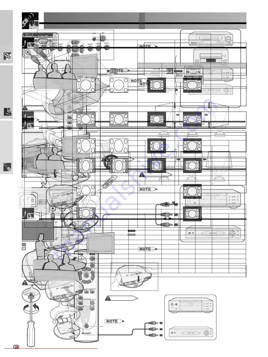
Setup & Connections
To S-video output terminal
To video output terminal
To component output
terminals
Component cable
(commercially available)
Connect each RCA connector of a component cable to the corresponding
RCA INPUT 1 terminals on the projector.
Connect the other end of the cable to the corresponding terminals on a DVD
player or DTV decoder.
Make sure to turn both the projector and the video equipment off, before
connecting.
S-video cable (commercially available)
Video cable
Connect the 3 RCA to 15-pin D-Sub cable to INPUT 2 COMPONENT/RGB port on the projector.
Use the above cables to connect the DTV decoder or DVD player.
When connecting this projector to analog RGB output of the DTV decoder, select Component for Signal Type on the
OSD menu or press
on the remote control. (See page 36.)
Make sure to turn both the projector and the video equipment off, before connecting.
3 RCA to 15-pin D-sub cable
(sold separately AN-C3CP)
Downloaded From projector-manual.com Sharp Manuals
Setup & Connections
The remote control can be used to control the projec-
tor within the range shown on the left.
The signal from the remote control can be reflected off a
screen for easy operation. However, the effective distance
of the signal may differ due to the screen material.
The backlights of the operation buttons can be turned
on for five seconds and off by pressing
. If you
want to turn off the backlights while they are on, press
again.
Connect one of the computer-RGB cable to the INPUT 2 COMPONENT/RGB port on the projector.
Connect the other end to the Corresponding terminal on a computer.
Make sure to turn both the projector and the video equipment off, before connecting.
Connect an RS-232C cable (null modem, cross type, commercially available) to the serial port on the computer.
Do not connect or disconnect an RS-232C cable to or from the computer while it is on. This may damage your computer.
Refer to Computer Compatibility Chart on page 54 for a list of computer signals compatible with the projector. Use with computer
signals other than those listed may cause some of the functions not to work.
The RS-232C function may not operate if your computer port is not correctly set up. Please refer to the operation manual of the computer for
details.
The arrows (
→
,
↔
) in the configuration above indicate the direction of the signals.
A Macintosh adaptor may be required for use with some Macintosh computers. Contact your nearest Sharp Authorised Projector Dealer or
Service Centre.
Computer-RGB cable
LIGHT button
Downloaded From projector-manual.com Sharp Manuals
Setup & Connections
You can adjust the angle and direction of the projected image by using
the Swivel Stand.
Unlock the lever on the Swivel Stand.
Adjust the angle and direction of the projected image as you want
by lifting up the projector and rotating the projector on the Swivel
Stand.
Lock the lever on the Swivel Stand.
Do not hold the lens when lifting, lowering or rotating the projector.
When lowering the projector, be careful not to get your fingers caught in the
area between the Swivel Stand and the projector.
When the height or direction of the projector is adjusted, the image may become
distorted (keystoned), depending on the relative positions of the projector
and the screen. See page 19 for details on the keystone correction.
Lift the projector (
) with pressing the removing-stand button on the
back of the projector (
).
Align the tabs on the front bottom of the projector (
). While holding
down the button (
), place the projector onto the Swivel Stand (
) to
attach.
Press the projector down firmly to attach
it to the Swivel Stand to make sure it is
securely attached to the Swivel Stand.
Adjustable up to
±10 from the
standard position.
Adjustable up to
±25 from the
standard position.
Adjustable up to
±3 from the
standard position.
Removing-
stand button
Downloaded From projector-manual.com Sharp Manuals
Setup & Connections
This function can be used to adjust the Keystone
settings.
For details about using the menu screen, see page 26.
Selected item
Description
Press
on the projector or on the
remote control.
Press
/
to select H Keystone or V
Keystone .
Press
/
to move the mark on the selected
adjustment item to the desired setting.
To return to the normal screen, press
again.
Straight lines and the edges of the displayed image may
appear jagged, when adjusting the Keystone setting.
When adjusting H Keystone and V Keystone at the same
time, the values of adjustable angles for each setting
become smaller.
The Digital Shift and Subtitle cannot be adjusted when
Keystone correction is applied.
Downloaded From projector-manual.com Sharp Manuals
Setup & Connections
Refer to pages 19 and 20 about the function of Keystone correction and placement of projector using the correction.
Decide the placement of the projector referring to the figures on the table and the diagram below according to the size of
your screen and the input signal.
± °
(a) Maximum projection distance
(b) Minimum projection distance
(c) Horizontal placement range when projection distance is maximum.
(d) Horizontal placement range when projection distance is minimum.
(e) Vertical placement range when projection distance is maximum.
(f) Vertical placement range when projection distance is minimum.
The aspect ratio of the projected image shifts slightly when the
lens shift is at a position other than the top position.
The aspect ratio of the projected image also shifts slightly
when the H Keystone and V Keystone functions are
adjusted simultaneously.
Keystone correction cannot be applied to On Screen Display.
When Keystone correction is applied, the resolution of image
can be deteriorated to some extent.
There are errors of ±3% in the formulas below.
Screen size
(4:3)( )
Projection distance and Keystone correction
Maximum projection distance
Minimum projection distance
Horizontal Placement range (d)
Diag.
508cm (200")
381cm (150")
254cm (100")
213cm (84")
183cm (72")
152cm (60")
102cm (40")
Horizontal Placement range (c)
Projection
distance (a)
9.3 m (30' 5")
6.2 m (20' 3")
5.2 m (16'12")
4.4 m (14' 5")
3.7 m (12' 1")
2.4 m (8')
Composite, S-video
480 /P, 1080
4.4 m (14' 5")
2.9 m (9' 6")
2.5 m (8' 2")
2.1 m (6'11")
1.7 m (5' 7")
1.1 m (3' 7")
720P
3.4 m (11' 2")
2.3 m
(7' 7")
1.9 m
(6' 3")
1.6 m
(5' 3")
1.3 m
(4' 3")
0.9 m
(2'11")
RGB
2.6 m (8' 6")
1.7 m (5' 7")
1.4 m (4' 7")
1.2 m (3'11")
1.0 m (3' 3")
0.6 m (1'12")
Vertical
placement range
(e)
2.1 m (6'11")
1.4 m (4' 7")
1.1 m (3' 7")
1.0 m (3' 3")
0.8 m (2' 7")
0.5 m (1' 8")
Projection
distance (b)
10.3 m (33' 9")
7.7 m (25' 4")
5.1 m (16'10")
4.3 m (14' 1")
3.7 m (12' 1")
3.1 m (10' 2")
2.0 m (6' 8")
Composite, S-video
480 /P, 1080
4.3 m (14' 1")
3.2 m(10' 6")
2.1 m (6'11")
1.8 m (5'11")
1.5 m (4'11")
1.2 m (3'11")
0.8 m (2' 7")
720P
3.1 m (10' 2")
2.3m
(7' 7")
1.5m
(4'11")
1.3 m (4' 3")
1.1m
(3' 7")
0.9 m (2'11")
0.6 m (1'12")
RGB
2.6 m (8' 6")
1.9 m (6' 3")
1.3 m (4' 3")
1.0 m (3' 3")
0.9 m (2'11")
0.7 m (2' 4")
0.5 m (1' 8")
Vertical
placement range
(f)
2.3 m (7' 7")
1.7 m (5' 7")
1.1 m (3' 7")
0.9 m (2'11")
0.8 m (2' 7")
0.7 m (2' 4")
0.4 m (1' 4")
Screen size
(16:9)( )
Projection distance and Keystone correction
Maximum projection distance
Minimum projection distance
Diag.
508cm (200")
381cm (150")
338cm (133")
269cm (106")
254cm (100")
234cm (92")
213cm (84")
183cm (72")
152cm (60")
102cm (40")
Projection
distance (a)
13.5 m (44' 3")
10.1 m (33' 2")
9.0 m (29' 5")
7.1 m (23' 5")
6.7 m (22' 1")
6.2 m (20' 3")
5.6 m (18' 6")
4.8 m (15' 9")
4.0 m (13' 2")
2.7 m (8'10")
Composite, S-video
480 /P, 1080
6.5 m (21' 4")
4.8 m (15' 9")
4.3 m (14' 1")
3.4 m (11' 2")
3.2 m (10' 6")
3.0 m
(9'10")
2.7 m
(8'10")
2.3 m
(7' 7")
1.9 m
(6' 3")
1.3 m
(4' 3")
720P
5.0 m (16' 5")
3.7 m (12' 2")
3.3 m (10'10")
2.6 m
(8' 6")
2.5 m
(8' 2")
2.3 m
(7' 7")
2.0 m
(6' 7")
1.7 m
(5' 7")
1.4 m
(4' 7")
1.0 m
(3' 3")
RGB
3.8 m (12' 6")
2.8 m (9' 2")
2.5 m (8' 2")
2.0 m (6' 7")
1.8 m (5'11")
1.7 m (5' 7")
1.5 m (4'11")
1.3 m (4' 3")
1.1 m (3' 7")
0.7 m (2' 4")
Vertical
placement range
(e)
3.1 m (10' 2")
2.3 m
(7' 7")
2.0 m
(6' 7")
1.6 m
(5' 3")
1.5 m
(4'11")
1.4 m
(4' 7")
1.2 m
(3'11")
1.1 m
(3' 7")
0.9 m
(2'11")
0.6 m
(1'12")
Projection
distance (b)
11.2 m (36'10")
8.4 m (27' 7")
7.4 m (24' 5")
5.9 m (19' 5")
5.6 m (18' 4")
5.1 m (16'10")
4.7 m (15' 5")
4.0 m (13' 2")
3.3 m (10'10")
2.2 m (7' 3")
Composite, S-video
480 /P, 1080
4.7 m (15' 5")
3.5 m (11' 6")
3.1 m (10' 2")
2.4 m (7'10")
2.3 m (7' 7")
2.1 m (6'11")
1.9 m (6' 3")
1.6 m (5' 3")
1.3 m (4' 3")
0.9 m (2'11")
720P
3.4 m (11' 2")
2.5 m (8' 2")
2.2 m (7' 3")
1.8 m (5'11")
1.7 m (5' 7")
1.5 m (4'11")
1.4 m (4' 7")
1.2 m (3'11")
1.0 m (3' 3")
0.6 m (1'12")
RGB
2.8 m (9' 2")
2.1 m (6'11")
1.8 m (5'11")
1.5 m (4'11")
1.4 m (4' 7")
1.3 m (4' 3")
1.2 m (3'11")
1.0 m (3' 3")
0.8 m (2' 7")
0.5 m (1' 8")
Vertical
placement range
(f)
2.5 m (8' 2")
1.9 m (6' 3")
1.7 m (5' 7")
1.3 m (4' 3")
1.2 m (3'11")
1.1 m (3' 7")
1.0 m (3' 3")
0.9 m (2'11")
0.7 m (2' 4")
0.5 m (1' 8")
Horizontal Placement range (c)
Horizontal Placement range (d)
Downloaded From projector-manual.com Sharp Manuals
Setup & Connections
Rear Projection
Place a translucent screen between the projector and
the audience.
Use the projector s menu screen to reverse the
projected image. (See page 42 for use of this
function.)
Optimal image quality can be achieved when the projector
is positioned perpendicular to the screen with all feet flat
and leveled.
Projection Using a Mirror
When the distance between the projector and a
screen is not sufficient for normal rear projection, you
can use a mirror to reflect the image onto the screen.
Place a mirror (normal flat type) in front of the lens.
Project the normal image onto the mirror.
The image reflected from the mirror is projected onto
the translucent screen.
CAUTION
When using a mirror, be sure to carefully position both the
projector and the mirror so the light does not shine into the
eyes of the audience.
It is recommended that you use the optional Sharp
ceiling-mount bracket for this installation.
Before mounting the projector, remove the Swivel
Stand. (See page 17 for removing and attaching the
Swivel Stand.)
Before mounting the projector, contact your nearest
Sharp Authorised Projector Dealer or Service Centre
to obtain the recommended ceiling-mount bracket
(sold separately). (AN-TK202 ceiling-mount bracket,
AN-TK201 extension tube, AN-60KT ceiling adaptors
for AN-TK202 or AN-TK201)
When the projector is in the inverted position, use the
upper edge of the screen as the base line.
Use the projector s menu screen to select the
appropriate projection mode. (See page 42 for use
of this function.)
Ceiling-mount Projection
Image Projection
Downloaded From projector-manual.com Sharp Manuals
Operation Buttons
Adjusting the Picture Aspect Ratio


