background image

SERVICE MANUAL

COPYRIGHT © 2006 Victor Company of Japan, Limited

No.YA455

2006/8

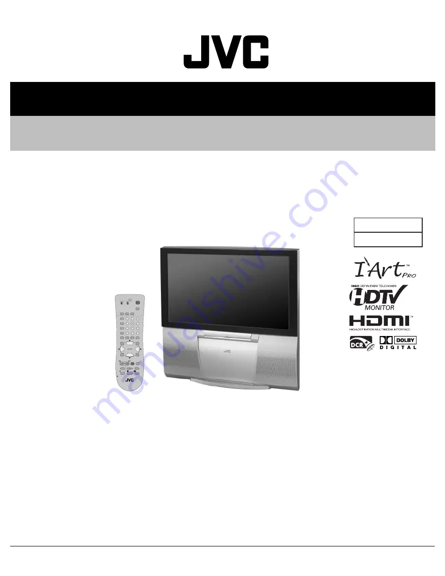
REAR PROJECTION TELEVISION

YA455

2006

8

AV-48P777

/H

, AV-48P787

/H

AV-56P777

/H

, AV-56P787

/H

TABLE OF CONTENTS

1

PRECAUTION. . . . . . . . . . . . . . . . . . . . . . . . . . . . . . . . . . . . . . . . . . . . . . . . . . . . . . . . . . . . . . . . . . . . . . . . .  1-3

2

SPECIFIC SERVICE INSTRUCTIONS . . . . . . . . . . . . . . . . . . . . . . . . . . . . . . . . . . . . . . . . . . . . . . . . . . . . . .  1-5

3

DISASSEMBLY  . . . . . . . . . . . . . . . . . . . . . . . . . . . . . . . . . . . . . . . . . . . . . . . . . . . . . . . . . . . . . . . . . . . . . .  1-10

4

ADJUSTMENT . . . . . . . . . . . . . . . . . . . . . . . . . . . . . . . . . . . . . . . . . . . . . . . . . . . . . . . . . . . . . . . . . . . . . . .  1-20

5

TROUBLESHOOTING . . . . . . . . . . . . . . . . . . . . . . . . . . . . . . . . . . . . . . . . . . . . . . . . . . . . . . . . . . . . . . . . .  1-44

BASIC CHASSIS

SR2

POWER

THEATER PRO

VIDEO STATUS

SLEEP
TIMER

FAVORITE

SUB CH

1

7

4

TUNE

3

9

6

/TV

MUTING

MENU

OK

BACK

2

8

0

5

CH +

VOL

VOL

+

REC

OPEN/CLOSE

STILL/PAUSE

STOP

PAUSE

PLAY

FF

REW

TV CATV VCR

DVD

VCR CHANNEL

PREV  NEXT

TV/VCR

VCR/

DVD

POWER

ASPECT

CH –

TV

RM-C1272G

ML/MTS SOUND

GUIDE

DISPLAY

C.C.

INPUT

Summary of Contents for AV-48P777/H

Page 1: ...SPECIFIC SERVICE INSTRUCTIONS 1 5 3 DISASSEMBLY 1 10 4 ADJUSTMENT 1 20 5 TROUBLESHOOTING 1 44 BASIC CHASSIS SR2 POWER THEATER PRO VIDEO STATUS SLEEP TIMER FAVORITE SUB CH 1 7 4 TUNE 3 9 6 RETURN TV MUTING MENU OK BACK 2 8 0 5 CH VOL VOL REC OPEN CLOSE STILL PAUSE STOP PAUSE PLAY FF REW TV CATV VCR DVD VCR CHANNEL PREV NEXT TV VCR VCR DVD POWER ASPECT CH TV RM C1272G ML MTS SOUND GUIDE DISPLAY C C ...

Page 2: ...reen Size 48 122cm Measured diagonally W 106 3 cm H 59 8 cm 16 9 ratio 56 142cm Measured diagonally W 124 cm H 69 8 cm 16 9 ratio Projection Tube 17cm 6 7 tube 3 R G B High Voltage 31 6kV 1 0kV 1 5kV at zero beam current Speaker 13cm round type 2 Audio Power Output 7W 7W Full range Antenna Terminal VHF UHF ATSC DIGITAL CABLE IN 75Ω unbalanced coaxial F type connector 1 Video Audio Input INPUT 1 2 ...

Page 3: ...r adjusted See ADJUSTMENT OF B1 POWER SUPPLY 8 Do not check high voltage by drawing an arc Use a high voltage meter or a high voltage probe with a VTVM Discharge the picture tube before attempting meter connection by connecting a clip lead to the ground frame and connecting the other end of the lead through a 10kΩ 2W resistor to the anode button 9 When service is required observe the original lead...

Page 4: ...ey the CONVERGENCE menu appears 3 Press the function up down key and select the MANUAL 4 Press the function left right key then CONVERGENCE adjustment screen appear Fig 1 If all the crosses are white no convergence adjustment is needed 5 Select the location you want to adjust by using the number 2 4 5 6 8 keys on the remote control unit Fig 2 6 Press the SLEEP TIMER key to change the color of the ...

Page 5: ...L INPUT Digital in will display when any picture signal in Digital in is displayed V CHIP Since the V CHIP is built in it can choose view and listen to a healthy program MTS STEREO The voice multiplex function of the MTS system is built in MTS Multi channel Television Sound system NATURAL CINEMA Watching the movie or animation press the Natural Cinema to adjust the out line of the images to make t...

Page 6: ... Not used Low speed oscillator 71 P74 SBI1 Not used 22 VDD I 3 3V 72 P75 SBO1 Not used 23 OSCI I Oscillation for system clock 16MHz 73 SBD5 I O On board writing for flash memory 24 OSCO O Oscillation for system clock 16MHz 74 SBT5 I On board writing for flash memory 25 MODE I Single chip mode for CPU H Fixed 75 NMI I 3 3V 26 TU_POWER O Not used Power control for tuner 76 HDMI_CEC O Not used 27 P25...

Page 7: ... SSR0K050A M2 SSR0K051A M2 6 REMOTE SENSOR PWB SSR 8010A M2 7 R CRT SOCKET PWB SSR 3151A M2 8 G CRT SOCKET PWB SSR 3251A M2 9 B CRT SOCKET PWB SSR 3351A M2 10 FRONT CONTROL PWB SSR0L015A M2 11 USB PWB SSR 7561A M2 AV TERMINAL BOARD This figure is only MAIN UNIT 4 3 DEF CONVERGENCE OUT PWB POWER PWB 11 USB PWB 1 MAIN PWB 8 9 G CRT SOCKET PWB B CRT SOCKET PWB 2 ATSC TUNER PWB PROJECTION UNIT FRONT C...

Page 8: ...side upwards and sure to place spacers between the screen and resting site floor or stand etc to prevent the screen from sagging 2 6 2 SCREEN SURFACE Since the screen surface is easily scratched or soiled use ample care when handling Leave the screen with protector fresnel lens and double lenticular lens attached If cannot be disassembled further SCREEN FRONT PANEL SCREEN BRACKET BOTTOM SCREEN BRA...

Page 9: ...e not to be disassembled during service When replacing projection unit parts disassemble to the state indicated in the figure below The figure indicates screws and wires that are not to be removed Use care not to remove these LENS ASS Y SCREW x 4 LENS ASS Y CRT ASS Y COUPLER ASS Y DEF CONVER YOKE TAPE 2 4 POLE MAGNET R CRT SOCKET PWB ASS Y G CRT SOCKET PWB ASS Y B CRT SOCKET PWB ASS Y Check that t...

Page 10: ...ove the SPEAKER GRILL Remove the FRONT PANEL 1 Remove 5 screws D 2 Remove the FRONT CONTROL BOX 3 1 5 REMOVING THE FRONT CONTROL PWB Fig 1 Remove the SPEAKER GRILL Remove the FRONT PANEL Remove the FRONT CONTROL BOX 1 Remove 2 screws E 2 Remove 3 screws F from rear side of FRONT CONTROL BOX 3 Remove the FRONT CONTROL PWB 3 1 6 REMOVING THE SCREEN ASS Y Fig 1 Remove the SPEAKER GRILL Remove the FRO...

Page 11: ...screws L from front side 3 Slightly pull for backside to disengage of the REAR COVER from hooks 4 Remove the REAR COVER NOTE Because of the large size at least 2 persons are recommended for removal and reassemble 3 1 9 REMOVING THE REAR PANEL Fig 1 1 Remove 12 screws M 2 Remove the REAR PANEL 3 1 10 REMOVING THE PARTITION Fig 1 Remove the REAR PANEL 1 Pull out the PARTITION backward ...

Page 12: ... H K M M L L G D C E J F REAR COVER MIRROR MIRROR BRACKET MIRROR BRACKET SCREEN ASS Y SPEAKER GRILLE FRONT PANEL FRONT CONTROL BOX FRONT CONTROL PWB BODY SPEAKER SPEAKER PARTITION REAR PANEL SPEAKER GRILLE FRONT FRONT CONTROL BOX ...

Page 13: ...tc raise the MAIN UNIT with the front side down for the make of convenience 3 1 12 REMOVING THE FOCUS PACK Fig 2 Remove the SPEAKER GRILL Remove the FRONT PANEL Remove the FRONTCONTROL BOX Remove the REAR PANEL Remove the MAIN UNIT 1 Remove 1 screw Q 2 Remove the FOCUS PACK 3 Remove wires connecting the FOCUS PACK 3 1 13 REMOVING THE AV TERMINAL BOARD Fig 2 Remove the REAR PANEL 1 Remove 6 screws ...

Page 14: ...iginal positions Performance can be affected if these are not returned to the original posi tions 3 1 20 REMOVING THE HV DIVIDER Fig 2 Remove the REAR PANEL 1 Remove 1 screw b 2 Remove the HV DIVIDER NOTE Wires of the transformer FBT and CRT of each PROJEC TION UNIT can be removed by turning the connector portions If necessary remove the anode wires and replacing the HV DIVIDER take care to correc...

Page 15: ...ODY MAIN CHASSIS FRONT SPEAKER CONNECTOR Fig 3 PROJECTION UNIT FOCUS PACK MAIN UNIT POWER PWB COOLANT PAN ATSC TUNER PWB MAIN PWB USB PWB AV TERMINAL BOARD MAIN CHASSIS POWER CORD POWER CORD CLAMP DEF CONVERGENCE OUT PWB DIGITAL CONVERGENCE MODULE PWB REMOTE SOENSOR PWB HV DIVIDER a N P Y Z W X ...

Page 16: ...he power cord to the wall outlet and switch on the power 4 Receiving channel setting Refer to the OPERATING INSTRUCTIONS USER S GUIDE and set the receive channels Channels Preset as described 5 User settings Check the user setting items according to the FACTORY SETTING ITEM table Where these do not agree refer to the OPERATING INSTRUCTIONS USER S GUIDE and set the items as described 6 SERVICE MODE...

Page 17: ... Digital Tunig Test TV Micro Service 1 Adjust 2 White Balance 3 Memory Edit Conver Service Conver Service 1 Coarse Adjust 2 Fine Adjust 3 Conver Off Press 1 key Press 2 key Press 3 key Setting items Settings Item No 1 Digital Service Audio system setting Adjust A001 A010 2 TV Micro Service Video system setting Adjust S001 S060 Deflection system Adjust D001 D071 Factory system setting Fixed F001 3 ...

Page 18: ...FF MTS STEREO ASPECT PANORAMA SOUND A H S OFF Smart Sound OFF Setting item Setting position Noise Muting On Language English Front Panel Lock Off V Chip Off Set Lock Code 0000 Closed Caption Auto CC1 T1 Auto Shut Off Off Power Indicator High Setting item Setting position Auto Tuner Setup Unnecessary to set Setting item Setting position Bass 0 Treble 0 Balance 0 Optical Out PCM Turn On Volume Curre...

Page 19: ...the tweezers and remove the chip part Transistors diodes variable resistors etc 1 Apply extra solder to each lead 2 As shown in the figure push the part with tweezers and alternately melt the solder at each lead Shift and remove the chip part Note After removing the part remove remaining solder from the pattern 2 How to install Chip parts Resistors capacitors etc 1 Apply solder to the pattern as i...

Page 20: ...G POSITION 4 2 MEASURING INSTRUMENT AND FIXTURES 1 DC voltmeter or digital voltmeter 2 Oscilloscope 3 Signal generator Pattern generator NTSC 4 TV audio multiplex signal generator 5 Remote control unit 6 Jig Remote Control Unit Parts number LP20873 009A NOTE Please order to your parts center if you do not have this remote control unit 4 3 ADJUSTMENT FLOWCHART WHEN REPLACING SCREEN AND PROJECTION U...

Page 21: ... 3 Conver Off 3 Edit Config 4 All Reset 5 Select Channel Map 2 TV Micro Service TV Micro Service 1 Adjust 2 White Balance 3 Memory Edit 1 Coarse Adjust 2 Fine Adjust 3 Conver Off 6 Clear Channel Map 7 Digital Tunig Test 2 Memory Edit Digital Memory Edit Digital Memory Edit Addr H 0000 Addr H 0000 0 1 2 3 4 5 6 7 0 1 2 3 4 5 6 7 04 01 06 58 FF FF FF FF 04 01 06 58 FF FF FF FF 8 9 A B C D E F 8 9 A ...

Page 22: ... data is not memorized to the memory IC And if exit the adjustment mode before memorize the data the adjustment value which you change is canceled 4 5 1 4 SERVICE MODE SELECT KEY LOCATION SERVICE MENU SCREEN Service Menu Service Menu 1 Digital Service 1 Digital Service 2 T 2 TV Micro Servic Micro Service 3 Co 3 Conver Servic er Service 4 Diagnostics 4 Diagnostics POWER THEATER PRO VIDEO STATUS SLE...

Page 23: ...t adjust CAUTION This mode is not used in the ADJUSTMENT Press the BACK key to return to the SERVICE MENU SCREEN NTSC 525i Composite S video input 525i 525i Component input 525p 525p Component input 750p 750p Component input 1125i 1125i Component input D525i ATSC 525i D525p ATSC 525p D750p ATSC 750p D1125i ATSC 1125i H525i HDMI 525i H525pS1 HDMI 525p size1 H525pS2 HDMI 525p size2 H750p HDMI 750p H...

Page 24: ... map is forcibly rewritten on this screen Do not adjust CAUTION This mode is not used in the ADJUSTMENT Press the BACK key to return to the SERVICE MENU SCREEN 6 Clear Channel Map Channel map is cleared on this screen Do not adjust CAUTION This mode is not used in the ADJUSTMENT Press the BACK key to return to the SERVICE MENU SCREEN 7 Digital Tuning Test Digital channel tuning is tested on this s...

Page 25: ...VALUE DATA Changed setting value is memorized by pressing MUTING key NTSC 525i Composite S video input 525i 525i Component input 525p 525p Component input 750p 750p Component input 1125i 1125i Component input D525i ATSC 525i D525p ATSC 525p D750p ATSC 750p D1125i ATSC 1125i H525i HDMI 525i H525pS1 HDMI 525p size1 H525pS2 HDMI 525p size2 H750p HDMI 750p H1125i HDMI 1125i 43Full FULL Input signal 4 ...

Page 26: ...IVE 2 key DRIVE R is up 5 key DRIVE R is down 3 key DRIVE B is up 6 key DRIVE B is down CUTOFF 1 key HORIZONTAL LINE on 4 key HORIZONTAL LINE off 7 key CUTOFF G is up TUNE key CUTOFF G is down 8 key CUTOFF R is up 0 key CUTOFF R is down 9 key CUTOFF B is up RETURN key CUTOFF B is down BR 054 DRV R031 B031 CUT R031 G031 B031 BRIGHTNESS DRIVE CUTOFF SETTING VALUE DATA TVM Memory Edit TVM Memory Edit...

Page 27: ...g is described in the CONVERGENCE adjustment 3 Conver Off For FOCUS BEAM SPOT adjustment or RASTER CENTERING adjustment 2 test patterns are selectable without convergence operation on this screen Press INPUT key to change the crosshatch pattern and the dot pattern SETTING ITEM NAME SETTING VALUE COARSE ADJUST MODE SETTING ITEM No CPA01 CPA11 CCA01 CCA12 CDA01 CDA07 CBA01 CBA111 CPA01 FINE OFF 0 CB...

Page 28: ... A006 AHS MVE 128 127 3 A007 AHS MSC 128 127 1 A008 AGC FLAT 0 3 1 A009 BBE BASS 128 127 0 A010 BBE TREB 128 127 0 No Setting item Variable range Initial setting value No Setting item Variable range Initial setting value RF EXTERNAL S CV STANDARD THEATER STANDARD S001 BRIGHT 000 063 031 S002 PICTURE 000 063 025 S003 COLOR 000 063 044 S004 TINT 000 063 031 S005 DETAIL 000 063 041 041 S006 BRIGHT 12...

Page 29: ...tting value RF EXTERNAL S CV EXTERNAL COMPONENT ATSC HDMI 525i 525p 1125i 750p S021 COL AXIS 000 003 002 002 S022 CB OFS 000 063 021 032 S023 CR OFS 000 063 032 032 S024 SYSTEM 000 003 003 003 003 003 003 S025 SHP F0 000 001 001 001 001 001 001 S026 SHP F1 000 003 001 001 001 001 001 No Setting item Variable range Initial setting value STANDARD THEATER S027 LTI LEV 000 003 002 002 S028 LTI MODE 00...

Page 30: ... TOP CORN 000 063 036 D017 TOP CO 128 127 000 D018 V EHT 000 015 000 D019 H EHT 000 015 005 D020 H CENT 000 063 030 D021 H CENT 128 127 000 D022 BOW 000 063 032 D023 BOW 128 127 000 D024 PARALLEL 000 063 029 D025 PARALL 128 127 000 D026 EW DC 000 001 000 D027 PIN COMP 000 007 000 D028 BOT UCP 000 003 000 D029 B UCP 128 127 000 D030 TOP UCP 000 003 000 D031 T UCP 128 127 000 D032 BOT UCG 000 003 00...

Page 31: ... 511 15 12 8 CCA11 C V KEY 512 511 0 114 77 CCA12 C TB PIN 512 511 280 153 230 No Setting item Variable range Initial setting value Full Cinema Regular Panorama No Setting item Variable range Initial setting value CDA01 DF DC 512 511 0 CDA02 DF H1 512 511 0 CDA03 DF H2 512 511 0 CDA04 DF V1 512 511 0 CDA05 DF V2 512 511 0 CDA06 DF V1H1 512 511 0 CDA07 DF V2H1 512 511 0 No Setting item Variable ran...

Page 32: ...ZE 0 255 116 CBA72 SQ5POSV 0 2047 547 CBA73 SQ5POSH 0 4095 1013 CBA74 SQ5VSIZE 0 255 70 CBA75 SQ5HSIZE 0 255 4 CBA76 SQ6POSV 0 2047 580 CBA77 SQ6POSH 0 4095 984 CBA78 SQ6VSIZE 0 255 4 CBA79 SQ6HSIZE 0 255 64 CBA80 SQ7POSV 0 2047 456 CBA81 SQ7POSH 0 4095 888 No Setting item Variable range Initial setting value CBA82 SQ7VSIZE 0 255 255 CBA83 SQ7HSIZE 0 255 255 CBA84 SQ8POSV 0 2047 0 CBA85 SQ8POSH 0 ...

Page 33: ...en picture disappears 4 Unplug the power cord 5 Remove the resistor 6 8kΩ from S1 connector 6 Again plug the power cord make sure that the normal picture is displayed on the screen HIGH VOLTAGE check Signal generator HV voltmeter CRT anode 1 Receive NTSC whole black signal 2 Connect the HV voltmeter between CRT anode and GND 3 Check the high voltage DC 31 6kV 1 0kV 1 5kV T502 FBT CN008 X RAY RESIS...

Page 34: ...focus in the top and the bottom on either side in the diagonal When the difference of the focus is big remove a main lens and put a washer between the main lens and the coupler and then re adjust it BEAM SPOT 5 Change dot pattern with INPUT key 6 Make a red single color 7 Turn the R FOCUS VR clockwise from just focus point to set the dot diameter to approx 30mm 8 Turn the 4 pole magnet of the proj...

Page 35: ...EBUT START DEBUT keys 4 In the same manner set the value to F using the STOP FIN STOP FIN keys 5 In the same manner set the value to E using the DATE DATE keys 6 In the same manner set the value to 1 using the PR PR keys 7 When completed with all of the above settings press the Transmission key 8 The code to switch on the convergence circuit is 0FE3 After adjustments you should transmit this code ...

Page 36: ...e a green single color NOTE When making a single color while adjusting of one CRT put the cap on other lens 5 Select D005 H SIZE and shorten the level until and perpendicular amplitude of vibration with until the blanking in Left and Right and on either side can be seen 6 Select D020 H CENT and adjust horizontal position to make the screen center and signal center same 7 Select D005 and adjust hor...

Page 37: ...onvergence circuit H POSITION adjustment Signal generator Remote control unit 1 Adjust D020 H CENT 1 Receive NTSC circle pattern signal 2 Select FULL mode with ASPECT key 3 Switch off the convergence circuit 4 Enter TV Micro Service 1 Adjust 5 Select D020 H CENT 6 Adjust D020 to make D E as shown figure 7 Press MUTING key to memorize the set value 8 After adjustment switch on the convergence circu...

Page 38: ...ly NOTE Refer to the FLOWCHART OF ADJUSTMENT for the way to switch off on the convergence circuit TRAPEZIUM adjustment Signal generator Remote control unit 1 Adjust D012 EW TRAP 1 Receive NTSC crosshatch signal 2 Select FULL mode with ASPECT key 3 Switch off the convergence circuit 4 Enter TV Micro Service 1 Adjust 5 Select D012 EW TRAP 6 Adjust D012 to bring the vertical lines at the right and le...

Page 39: ...ll be displayed on the screen 5 Check and set data CCA01 to CCA12 are same as the initial setting values 6 Press SLEEP TIMER key to change the adjusting color to red and blue 7 In the same manner check and set data for red and blue patterns 8 Press MUTING key to memorize the set values 9 Select CPA01 10 Change the CPA01 1 to 0 11 Press MUTING key to memorize the set values OVERALL CONVERGENCE POIN...

Page 40: ...ct the oscilloscope to TP R and S011 R CUTOFF adjust same manner as for 6 to 11 above 13 Connect the oscilloscope to TP B and S013 B CUTOFF adjust same manner as for 6 to 11 above 14 Adjust SCREEN VR for RGB respectively so that the black 3 becomes faintly whitish NOTE If it is difficult to adjust the SCREEN precisely adjust the SCREEN VR for one of 3 colors while masking other 2 colors WHITE BALA...

Page 41: ... value SUB CONTRAST adjustment 1 Remote control unit 1 Adjust S002 PICTURE Method of adjustment without measuring instrument 1 Receive any broadcast 2 Select STANDARD mode with VIDEO STATUS key 3 Set the COLOR TEMP is LOW mode 4 Enter TV Micro Service 1 Adjust 5 Select S002 PICTURE 6 Set the initial setting value 7 If the contrast is not the best with the initial setting value make fine adjustment...

Page 42: ...oscope Remote control unit TP R R CRT SOCKET PWB TP E GND 1 Adjust S003 COLOR S004 TINT Method of adjustment with measuring instrument 1 Receive NTSC color bar signal include 75 white 2 Select STANDARD mode with VIDEO STATUS key 3 Connect the oscilloscope to TP R 4 Enter TV Micro Service 1 Adjust 5 Select S003 COLOR and S004 TINT 6 Adjust S003 and S004 to be following setting value Refer to the ta...

Page 43: ...erator to the antenna terminal 2 Connect an oscilloscope to L OUT pin of the AUDIO OUT and display one cycle portion of the 300Hz signal 3 Change the connection of the oscilloscope to R OUT pin of the AUDIO OUT and enlarge the voltage axis 4 Enter Digital Service 1 Adjust 5 Select the A002 LOW SEP 6 Set the initial setting value of the A002 LOW SEP 7 Adjust the A002 so that the stroke element of t...

Page 44: ...STORY Failure history can be counted up to 9 times for each item When the number exceeds 9 display will remain as 9 Failure history will be stored in the memory unless it has been deleted 5 1 5 POINTS TO NOTE WHEN USING THE SELF CHECK FEATURE In addition to circuit failures abnormal operation the following cases may also be diagnosed as Abnormal and displayed and counted as NG 1 Temporary defectiv...

Page 45: ... of the photo sensor DIGI_PHOT At about 3 seconds after the power is turned on the self check function starts If NG is detected during 400ms irregularly is counted DTVM and TVM communication Hostlink Communication error between the digital TV microcomputer and the TV microcomputer is detected IC701 MAIN PWB SDA Check communication errors by counting the number of reset exception handling Fan lock ...

Page 46: ...rt protection the power of the TV is turned off when NG is detected Immediately after the power is turned off the POWER LED will be turning on and off When the power is turned off you cannot turn the power on again until the AC plug is taken out and put in again Item POWER LED ON OFF intervals X ray protection Turning on and off at 0 1 second intervals B1 over current protection Turning on and off...

Page 47: ... No YA455 Display Category 12 3 chome Moriya cho Kanagawa ku Yokohama city Kanagawa prefecture 221 8528 Japan Victor Company of Japan Limited VPT Printed in Japan ...

Reviews: