


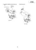


Mounting the connection gear, slow
brake and loading motor assemblies
(on the back of the mechanism chassis).
Assemble the connect gear.
Assemble the slow brake.
Assemble the loading motor unit.
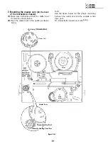
Note:
Let the slow brake leg out of the front of the
mechanism chassis. Catch the spring to the
up fixing guide that is at the left of the A/C head.
Slow
Brake
Figure
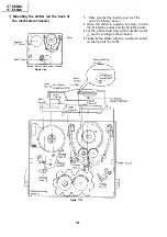
Note:
Before setting up the loading motor, make sure the
phase is matched. To do so, turn the connection
gear clockwise and check to see if the loading is
complete and if the pinch roller comes into contact.
When these actions are made smoothly, return the
mechanism to the state as shown above. Finally
mount the loading motor unit.
Summary of Contents for VT-3428X
Page 78: ...m 3428X VT 51 28X IF Pack Unit RiWOOl7CEZZ 1 4 11 l e i t 1 I 2 I 3 I 4 I 5 I 6 1 78 ...
Page 82: ...VT 3428X VT 5128X I AWIO m I Au 10 f X I 7 I 8 I 9 I 10 I 11 I 12 I 82 ...
Page 90: ...VT 3428X VT 51 28X I t 7 I 8 I 9 I 10 I 11 I 12 I ...
Page 94: ...VT 3428X W 5128X 3 7 I 8 I 9 I 10 I 11 I 12 I 94 ...
Page 96: ...VT 3428X VT 51 28X TO Y C AUDIO CIRCUIT NCR 21 I I I I 7 I 8 I 9 I 10 I 11 I 12 I 96 ...
Page 100: ...m 3428X VT 51 28X Wiring Side f r 7 I 8 I 9 I 10 I 11 I 12 1 100 ...
Page 102: ...VT 3428X VT 51 28X I 7 I 8 I 9 I 10 I 11 102 1 12 I ...
Page 104: ...VT 3428X I m 5128X 1 7 I 8 I 9 I 10 I 11 I 12 I ...
Page 123: ...MECHANISM CHASSIS PARTS G F E I i 1 I 2 I 3 I 4 I 5 I 6 I 123 ...
Page 125: ...CASSETTE HOUSING CONTROL PARTS i T 3428X VT 51 28X 1 I 2 I 3 I 4 I 5 I 6 I 125 ...
Page 127: ...VT 3428X W 51 28X MODIEL VT 3428X CABINET AND MECHANICAL PARTS 1 I 2 I 3 I 4 I 5 I 6 127 ...
Page 128: ...W 3428X VT 51 28X I IO 9 0 3 7 128 ...
Page 130: ...VT 3428X VT 5128X I 0 I 0 ...
Page 132: ...MODELS VT 3428X AND VT 51 28X CABINET AND MECHANICAL PARTS I i 1 I 2 I 3 I 4 I 5 I 6 I 132 ...
Page 136: ...S H A R P TQ0023 S Printed in Japan 0 w s MW KD ...