
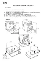
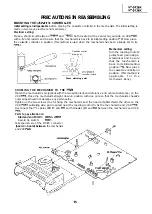


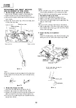


PRECAUTIONS IN REASSEMBLING
MOUNTING THE
CONTROLLER
Initial setting is indispensable
before placing the cassette controller in the mechanism. The initial setting is
made in two ways; electrical and mechanical.
Electrical setting:
Make a short-circuit between
and
both located at the center on your side on VCR
with a ohm resistor and be sure that the mechanism is back to its initial setting position
Now place
the cassette controller in position. (This method is used when the mechanism has been already set on its
Cassette control
drive gear
Phase matching point
Mechanical setting:
Turn the loading motor’s
pulley feed gear using a
screwdriver and be sure
that the mechanism is
back to its initial setting
position
Now place
the cassette controller in
position. (This method is
applicable
f o r t h e
mechanism alone.)
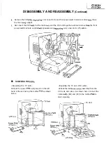
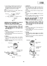
COUPLING THE MECHANISM TO THE
Match the mechanism’s projections with the two symbols (round reference and oval sub-reference) on the
VCR
Place the mechanism straight down in position with due care so that the mechanism chassis’s
outer edges should not damage any parts nearby.
Tighten up the two screws (one for fixing the mechanism and the head amplifier shield, the other on the
VCR
soldering side and located near the loading motor) to fix the mechanism and VCR
Reconnect the
cables
and
and harnesses (ED and
between the mechanism and VCR
Parts to pay attention to:
Start and end
Record tip switch:
Take special care of the MC-EC connector
(board
to
board) between
the mechanism
and VCR
Summary of Contents for VT-3428X
Page 78: ...m 3428X VT 51 28X IF Pack Unit RiWOOl7CEZZ 1 4 11 l e i t 1 I 2 I 3 I 4 I 5 I 6 1 78 ...
Page 82: ...VT 3428X VT 5128X I AWIO m I Au 10 f X I 7 I 8 I 9 I 10 I 11 I 12 I 82 ...
Page 90: ...VT 3428X VT 51 28X I t 7 I 8 I 9 I 10 I 11 I 12 I ...
Page 94: ...VT 3428X W 5128X 3 7 I 8 I 9 I 10 I 11 I 12 I 94 ...
Page 96: ...VT 3428X VT 51 28X TO Y C AUDIO CIRCUIT NCR 21 I I I I 7 I 8 I 9 I 10 I 11 I 12 I 96 ...
Page 100: ...m 3428X VT 51 28X Wiring Side f r 7 I 8 I 9 I 10 I 11 I 12 1 100 ...
Page 102: ...VT 3428X VT 51 28X I 7 I 8 I 9 I 10 I 11 102 1 12 I ...
Page 104: ...VT 3428X I m 5128X 1 7 I 8 I 9 I 10 I 11 I 12 I ...
Page 123: ...MECHANISM CHASSIS PARTS G F E I i 1 I 2 I 3 I 4 I 5 I 6 I 123 ...
Page 125: ...CASSETTE HOUSING CONTROL PARTS i T 3428X VT 51 28X 1 I 2 I 3 I 4 I 5 I 6 I 125 ...
Page 127: ...VT 3428X W 51 28X MODIEL VT 3428X CABINET AND MECHANICAL PARTS 1 I 2 I 3 I 4 I 5 I 6 127 ...
Page 128: ...W 3428X VT 51 28X I IO 9 0 3 7 128 ...
Page 130: ...VT 3428X VT 5128X I 0 I 0 ...
Page 132: ...MODELS VT 3428X AND VT 51 28X CABINET AND MECHANICAL PARTS I i 1 I 2 I 3 I 4 I 5 I 6 I 132 ...
Page 136: ...S H A R P TQ0023 S Printed in Japan 0 w s MW KD ...