


Push the
or tracking button to check
that
a
flat response is obtained on the
envelope waveform.
the guide roller by tightening the
guide roller setscrew in the unloading mode.
Play back the tape drive train alignment tape
to check that the envelope waveform does
not change.
Adjustment of A/C head X-position.
a) In the X value adjustment mode (see the
Electrical Adjustment), make a short circuit
between
and
both located at
the on your side on the VCR
with a
ohm resistor to center the tracking.
Rotate the X-position adjusting nut with an
adjusting box driver, and adjust the A/C head
position for maximum head switching pulse
low side envelope.
Adjust the playback switching point.
Check the flatness of the envelope waveform
and sound by playing back a recorded tape.
X-position adjusting nut
Main chassis
Figure
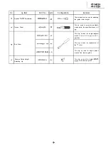
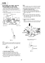
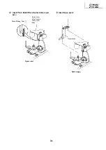
REPLACEMENT OF THE CAPSTAN
(DIRECT DRIVE) MOTOR
Remove the cassette housing control assembly.
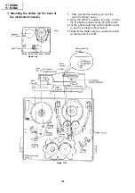
R e m o v a l ( F o l l o w t h e o r d e r o f i n d i c a t e d
numbers.)
Disconnect from the board-to-board connector
on the VCR
Remove the reel belt
Remove the screws
Figure
Figure
l
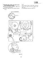
Reassembly
Mount the capstan motor on the mechanism
chassis making sure not to allow the capstan
shaft to hit the mechanism chassis, and attach it
with the three screws.
Attach the reel belt. Reconnect to the board-to
board connector on the VCR
Notes :
After installing the capstan
motor, be sure
to rotate the capstan
motor and check the
movement.
Check the servo circuit.
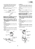
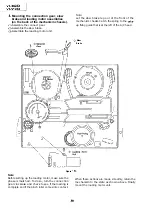
REPLACEMENT OF
MOTOR
Put the unit in the cassette eject position.
Unplug the power cord.
l
Removal (Reverse the order in reassembly.)
Disconnect the
cable
Unscrew the
assembly fixing screws
Take out the
assembly
Unscrew the rotor assembly fixing screws
Take out the rotor assembly
Notes:
In removing the
assembly, part of the
drum earth spring pops out of the
collar.
Be careful not to lose it.
Secure the
rotor assembly so that the
installation positioning holes in the rotor
assembly and upper drum assembly match.
(Match the upper drum’s notch with the rotor’s
hole.)
Be careful not to damage the upper drum or the
video head.
Be sure that the hall device and the
assembly are not damaged by the rotor assembly
or other parts.
After installation, adjust the playback switching
point.
2
motor
Summary of Contents for VT-3428X
Page 78: ...m 3428X VT 51 28X IF Pack Unit RiWOOl7CEZZ 1 4 11 l e i t 1 I 2 I 3 I 4 I 5 I 6 1 78 ...
Page 82: ...VT 3428X VT 5128X I AWIO m I Au 10 f X I 7 I 8 I 9 I 10 I 11 I 12 I 82 ...
Page 90: ...VT 3428X VT 51 28X I t 7 I 8 I 9 I 10 I 11 I 12 I ...
Page 94: ...VT 3428X W 5128X 3 7 I 8 I 9 I 10 I 11 I 12 I 94 ...
Page 96: ...VT 3428X VT 51 28X TO Y C AUDIO CIRCUIT NCR 21 I I I I 7 I 8 I 9 I 10 I 11 I 12 I 96 ...
Page 100: ...m 3428X VT 51 28X Wiring Side f r 7 I 8 I 9 I 10 I 11 I 12 1 100 ...
Page 102: ...VT 3428X VT 51 28X I 7 I 8 I 9 I 10 I 11 102 1 12 I ...
Page 104: ...VT 3428X I m 5128X 1 7 I 8 I 9 I 10 I 11 I 12 I ...
Page 123: ...MECHANISM CHASSIS PARTS G F E I i 1 I 2 I 3 I 4 I 5 I 6 I 123 ...
Page 125: ...CASSETTE HOUSING CONTROL PARTS i T 3428X VT 51 28X 1 I 2 I 3 I 4 I 5 I 6 I 125 ...
Page 127: ...VT 3428X W 51 28X MODIEL VT 3428X CABINET AND MECHANICAL PARTS 1 I 2 I 3 I 4 I 5 I 6 127 ...
Page 128: ...W 3428X VT 51 28X I IO 9 0 3 7 128 ...
Page 130: ...VT 3428X VT 5128X I 0 I 0 ...
Page 132: ...MODELS VT 3428X AND VT 51 28X CABINET AND MECHANICAL PARTS I i 1 I 2 I 3 I 4 I 5 I 6 I 132 ...
Page 136: ...S H A R P TQ0023 S Printed in Japan 0 w s MW KD ...