
SM-SX1/SX1W
– 9 –
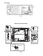
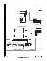
Output
Connector
-22V Side
-22V Side
+22V Side
+22V Side
semifixed VOL
semifixed VOL
G
A
From Main PWB
Output
Connector
1-bit PWB adjusting method
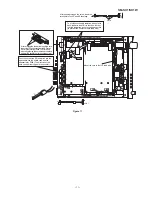
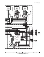
Connect as shown Fig. 9-2.
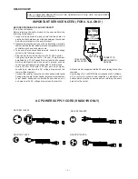
AC IN 110-120, 220-240, 230V
AC POWER SUPPLY
UNIT
Digital Multimeter
Figure 9-2
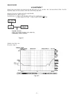
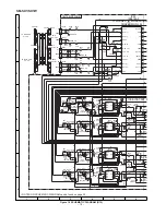
AC/DC switching power supply, Output voltage adjustment
Figure 9-1
Check that the AC/DC output voltage is
±
22V
±
0.15V at the
A
connector. (If different, adjust the voltage using the semifixed
VOL as described above.)
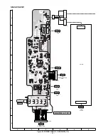
[Simplified offset voltage adjustment]
1. It is fitted to the mechanical center of VRA1, VRA2, VRA3, and VRA4.(FIg. 10-1)
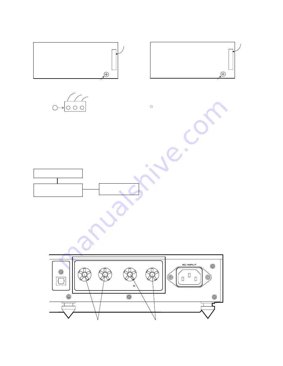
2. Connect the digital multimeter to the terminals of the speaker, and adjust the voltage b and – of each terminal to 0
±
10 mVolt with VRA1 (L-ch) or VRA2 (R-ch). (Fig.9-3)
DIGITAL OUT
(OPTICAL)
RIGHT
+
-
RATED IMPEDANCE : 8
SPEAKERS
LEFT
+
-
R-ch 8
Ω
SP Terminal L-ch
Figure 9-3


