


SM-SX1/SX1W
– 31 –
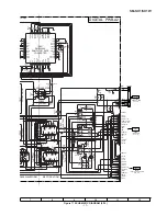
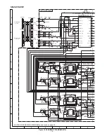
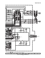
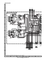
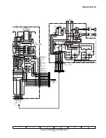
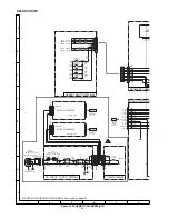
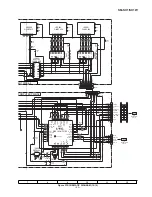
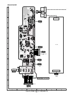
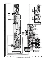
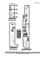
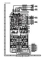
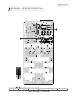
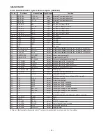
Figure 31 WIRING SIDE OF P.W.BOARD (8/8)
7
8
9
10
11
12
IC908
R914
R921
R920
R919
R918
R922
D900
R924
R925
R926
IC907
R929
R936
R974
R937
R946
R940
R950
R943
R947
R953
R957
R955
R952
R951
R917
R954
R958
R956
R973
C905
C907
C906
IC904
IC903
IC905
R970
R968
R969
R967
1
9
5
15
10
18
10
9
1
18
15
5
23
33
34
35
30
25
20
15
12
22
11
10
5
1
44
40
1
3
5 4
L901
L902
L903
SEGMENT PWB-A5(BOTTOM)
SELECT SWITCH
PWB-A7(BOTTOM)
MICROCOMPUTER
PWB-A-8(BOTTOM)
AC INPUT FILTER
PWB-A6(BOTTOM)
18
1
9
10
15
5
B R
COLOR TABLE
R D ( R )
O R
Y L
G R
B L
V L
G Y
W H ( W )
B K
P K
BROWN
RED
ORANGE
YELLOW
GREEN
BLUE
VIOLET
GRAY
WHITE
BLACK
PINK
: Through-hole where the top and bottom patterns are connected.


