20
PZ-43MR2E
PZ-50MR2E
Æ
Description of Main ICs
»
»»
»»
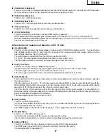
IC1301 (CXA2069Q)
This IC is a 7-input, 3-output selector.
The video signals other than those for the PC, components and RGB input, which have been input from each input
connector and the tuner, and all the audio signals are sent to the IC1301 and then selected.
Output 1 is used internally and output 3 in the monitor output.
When the S video input is output to the monitor, Y and C signals are mixed in this IC.
The video signals sent to the IC1301 are then input to the YC separation circuits, IC405 (main) and IC402 (sub).
The audio signals are input to the PC I/F Unit via IC2501 (sound processor).
»
»»
»»
IC1401 (MM1519XQ)
This IC is a 4-input, 8-output video selector for component input.
The AV3 component input, AV1, RGB input, and Teletext RGB signals are input to the IC1401. The output signals
go to the main, sub, and component channels.
»
»»
»»
IC1601 (SDA5550M).
This IC is a microprocessor for Teletext.
Video signals are input to the IC1601, which then decodes the Teletex data and outputs it as RGB data.
»
»»
»»
IC2501 (IX3371CE)
This IC is used to decode audio signals.
It serves as both the S IF decoder and the selector for the input audio data.
»
»»
»»
IC801/IC802 (TB1274AF)
This IC synchronizes video and chroma signals for PAL/NTSC/SECAM colour televisions.
Its video circuit includes a high-performance image quality compensation circuit and its chroma circuit a PAL/
NTSC/SECAM automatic selection circuit. The PAL-M/N clock signals at 4.43 and 8.58 MHz are internally generated
for colour demodulation.
The PAL/SECAM demodulation circuit uses a base band signal processing system with built-in IH DL and is
therefore adjustment-free.
The IC801/IC802 has 4 lines for YC signal input, 2 lines for RGB signal input, and 2 lines for colour difference
signal input. It receives colour different signals for the main and sub channels from IC405 (main), IC402 (sub), and
IC1401 in the former stage, and provides 1 line for colour difference signal output.
»
»»
»»
IC803 (CXA2101Q)
This IC consists of a base band signal processing section for colour different input, an RGB signal processing
section, and a 4-line video switch (including HV synchronizing signal processing).
Input selection is performed by INPUT-SEL (I
2
C BUS). YCbCr, HD YPbPr, GBR and their respective HV synchronizing
signals are input to each line.
As the multi-scanning compliance range, a horizontal scanning frequency of 15~60 kHz can be input.
»
»»
»»
IC1901 (IX3566CE)
This IC is FPGA for the synchronizing system.
It creates sand castle pulses for IC803 and generates horizontal blanking signals.
»
»»
»»
IC604 (TA1318AF)
This IC synchronizes TV component signals.
The IC804 incorporates the necessary functions for measuring the frequency of input signals and synchronous
replay into a single chip, and is applicable for horizontal synchronous replay (15.75, 31.5, 33.75, and 45 kHz) and
vertical synchronous replay (525I, 525P, 625I, 750P, 1125I, 1125P, PAL 100 Hz, and NTSC 120 Hz).
DESCRIPTION OF MAJOR IC FUNCTIONS
Summary of Contents for PZ-43MR2E
Page 11: ...11 PZ 43MR2E PZ 50MR2E Dimensions Unit mm ...
Page 24: ...24 PZ 43MR2E PZ 50MR2E Ë VHiMM1519XQ 1 IC1401 Component Input Video Switch Block Diagram ...
Page 30: ...30 PZ 43MR2E PZ 50MR2E Ë VHiTB1274AF 1Q ASSY IC801 IC802 VIDEO CHROMA Processor Block Diagram ...
Page 35: ...35 PZ 43MR2E PZ 50MR2E Ë VHiTA1318AF 1 ASSY IC604 Sync Processor Block Diagram ...
Page 37: ...37 PZ 43MR2E PZ 50MR2E Ë VHiCXD2064Q 1 ASSY IC402 IC405 Digital Comb Filter Block Diagram ...
Page 41: ...41 PZ 43MR2E PZ 50MR2E Ë VHiFA3675F 1 ASSY IC1702 6 channel DC DC Converter IC Block Diagram ...
Page 52: ...52 8 7 10 9 6 5 4 3 2 1 A B C D E F G H PZ 43MR2E PZ 50MR2E SYSTEM BLOCK DIAGRAM ...
Page 53: ...53 17 16 19 18 15 14 13 12 11 10 PZ 43MR2E PZ 50MR2E ...
Page 54: ...54 8 7 10 9 6 5 4 3 2 1 A B C D E F G H PZ 43MR2E PZ 50MR2E SIGNAL FLOW BLOCK DIAGRAM ...
Page 55: ...55 17 16 19 18 15 14 13 12 11 10 PZ 43MR2E PZ 50MR2E ...
Page 56: ...56 8 7 10 9 6 5 4 3 2 1 A B C D E F G H PZ 43MR2E PZ 50MR2E DC DC CONVERTER BLOCK DIAGRAM ...
Page 57: ...57 17 16 19 18 15 14 13 12 11 10 PZ 43MR2E PZ 50MR2E ...
Page 58: ...58 8 7 10 9 6 5 4 3 2 1 A B C D E F G H PZ 43MR2E PZ 50MR2E POWER BLOCK DIAGRAM ...
Page 59: ...59 17 16 19 18 15 14 13 12 11 10 PZ 43MR2E PZ 50MR2E ...
Page 64: ...64 8 7 10 9 6 5 4 3 2 1 A B C D E F G H PZ 43MR2E PZ 50MR2E OVERALL WIRING DIAGRAM 2 2 ...
Page 65: ...65 17 16 19 18 15 14 13 12 11 10 PZ 43MR2E PZ 50MR2E ...
Page 68: ...68 8 7 10 9 6 5 4 3 2 1 A B C D E F G H PZ 43MR2E PZ 50MR2E Ë MAIN UNIT 1 6 ...
Page 69: ...69 17 16 19 18 15 14 13 12 11 10 PZ 43MR2E PZ 50MR2E ...
Page 70: ...70 8 7 10 9 6 5 4 3 2 1 A B C D E F G H PZ 43MR2E PZ 50MR2E Ë MAIN UNIT 2 6 ...
Page 71: ...71 17 16 19 18 15 14 13 12 11 10 PZ 43MR2E PZ 50MR2E ...
Page 72: ...72 8 7 10 9 6 5 4 3 2 1 A B C D E F G H PZ 43MR2E PZ 50MR2E Ë MAIN UNIT 3 6 ...
Page 73: ...73 17 16 19 18 15 14 13 12 11 10 PZ 43MR2E PZ 50MR2E ...
Page 74: ...74 8 7 10 9 6 5 4 3 2 1 A B C D E F G H PZ 43MR2E PZ 50MR2E Ë MAIN UNIT 4 6 ...
Page 75: ...75 17 16 19 18 15 14 13 12 11 10 PZ 43MR2E PZ 50MR2E ...
Page 76: ...76 8 7 10 9 6 5 4 3 2 1 A B C D E F G H PZ 43MR2E PZ 50MR2E Ë MAIN UNIT 5 6 ...
Page 77: ...77 17 16 19 18 15 14 13 12 11 10 PZ 43MR2E PZ 50MR2E ...
Page 78: ...78 8 7 10 9 6 5 4 3 2 1 A B C D E F G H PZ 43MR2E PZ 50MR2E Ë MAIN UNIT 6 6 ...
Page 79: ...79 17 16 19 18 15 14 13 12 11 10 PZ 43MR2E PZ 50MR2E ...
Page 80: ...80 8 7 10 9 6 5 4 3 2 1 A B C D E F G H PZ 43MR2E PZ 50MR2E Ë FRONT UNIT ...
Page 81: ...81 17 16 19 18 15 14 13 12 11 10 PZ 43MR2E PZ 50MR2E ...
Page 82: ...82 8 7 10 9 6 5 4 3 2 1 A B C D E F G H PZ 43MR2E PZ 50MR2E Ë AV UNIT 1 3 ...
Page 83: ...83 17 16 19 18 15 14 13 12 11 10 PZ 43MR2E PZ 50MR2E ...
Page 84: ...84 8 7 10 9 6 5 4 3 2 1 A B C D E F G H PZ 43MR2E PZ 50MR2E Ë AV UNIT 2 3 ...
Page 85: ...85 17 16 19 18 15 14 13 12 11 10 PZ 43MR2E PZ 50MR2E ...
Page 86: ...86 8 7 10 9 6 5 4 3 2 1 A B C D E F G H PZ 43MR2E PZ 50MR2E Ë AV UNIT 3 3 ...
Page 87: ...87 17 16 19 18 15 14 13 12 11 10 PZ 43MR2E PZ 50MR2E ...
Page 88: ...88 8 7 10 9 6 5 4 3 2 1 A B C D E F G H PZ 43MR2E PZ 50MR2E Ë SR Unit ...
Page 89: ...89 17 16 19 18 15 14 13 12 11 10 PZ 43MR2E PZ 50MR2E ...
Page 90: ...90 8 7 10 9 6 5 4 3 2 1 A B C D E F G H PZ 43MR2E PZ 50MR2E Ë LED Unit ...
Page 91: ...91 17 16 19 18 15 14 13 12 11 10 PZ 43MR2E PZ 50MR2E ...
Page 92: ...92 8 7 10 9 6 5 4 3 2 1 A B C D E F G H PZ 43MR2E PZ 50MR2E Ë PC I F Unit 1 7 ...
Page 93: ...93 17 16 19 18 15 14 13 12 11 10 PZ 43MR2E PZ 50MR2E ...
Page 94: ...94 8 7 10 9 6 5 4 3 2 1 A B C D E F G H PZ 43MR2E PZ 50MR2E Ë PC I F Unit 2 7 ...
Page 95: ...95 17 16 19 18 15 14 13 12 11 10 PZ 43MR2E PZ 50MR2E ...
Page 96: ...96 8 7 10 9 6 5 4 3 2 1 A B C D E F G H PZ 43MR2E PZ 50MR2E Ë PC I F Unit 3 7 ...
Page 97: ...97 17 16 19 18 15 14 13 12 11 10 PZ 43MR2E PZ 50MR2E ...
Page 98: ...98 8 7 10 9 6 5 4 3 2 1 A B C D E F G H PZ 43MR2E PZ 50MR2E Ë PC I F Unit 4 7 ...
Page 99: ...99 17 16 19 18 15 14 13 12 11 10 PZ 43MR2E PZ 50MR2E ...
Page 100: ...100 8 7 10 9 6 5 4 3 2 1 A B C D E F G H PZ 43MR2E PZ 50MR2E Ë PC I F Unit 5 7 ...
Page 101: ...101 17 16 19 18 15 14 13 12 11 10 PZ 43MR2E PZ 50MR2E ...
Page 102: ...102 8 7 10 9 6 5 4 3 2 1 A B C D E F G H PZ 43MR2E PZ 50MR2E Ë PC I F Unit 6 7 ...
Page 103: ...103 17 16 19 18 15 14 13 12 11 10 PZ 43MR2E PZ 50MR2E ...
Page 104: ...104 8 7 10 9 6 5 4 3 2 1 A B C D E F G H PZ 43MR2E PZ 50MR2E Ë PC I F Unit 7 7 ...
Page 105: ...105 17 16 19 18 15 14 13 12 11 10 PZ 43MR2E PZ 50MR2E ...
Page 106: ...106 8 7 10 9 6 5 4 3 2 1 A B C D E F G H PZ 43MR2E PZ 50MR2E Ë POWER and EMC Unit ...
Page 107: ...107 17 16 19 18 15 14 13 12 11 10 PZ 43MR2E PZ 50MR2E ...
Page 109: ...6 5 4 3 2 1 A B C D E F G H 109 PZ 43MR2E PZ 50MR2E MAIN Unit B Side ...
Page 110: ...6 5 4 3 2 1 A B C D E F G H 110 PZ 43MR2E PZ 50MR2E AV Unit Component Side ...
Page 112: ...6 5 4 3 2 1 A B C D E F G H 112 PZ 43MR2E PZ 50MR2E PC I F Unit A Side ...
Page 113: ...6 5 4 3 2 1 A B C D E F G H 113 PZ 43MR2E PZ 50MR2E PC I F Unit B Side ...


