background image

21

E

Menu Items

n

OTHERS

SCREEN MOTION
PATTERN

Residual images are reduced by moving the screen.

OFF ................. SCREEN MOTION function is disabled.

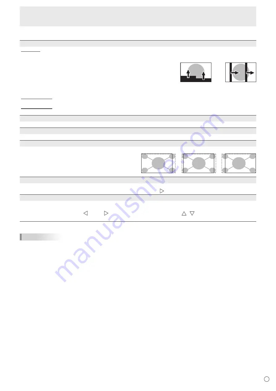
PATTERN1 ...... A black screen spreads from the bottom of the screen and then 

shrinks to the bottom of the screen. If the monitor is installed in the 

portrait orientation, a black screen spreads from the left end of the 

screen and then shrinks to the left end of the screen.

PATTERN2 ...... A black bar moves from the left end to the right end of the screen. 

If the monitor is installed in the portrait orientation, a black bar 

moves from the top to the bottom of the screen.

MOTION TIME 1

Specify a time period (operating interval) until SCREEN MOTION starts.

MOTION TIME 2

Specify a time period during which SCREEN MOTION operates (time period during which the screen will move).

POWER MANAGEMENT

POWER MANAGEMENT determines whether or not to switch modes from no signal to the input signal standby mode.

SIZE

Changes the screen size. (See page 17.)

4096 DISPLAY POSITION

Sets the position where the image is displayed (LEFT, CENTER, 

or RIGHT) when a signal with 4096 horizontal dots is input.

When RIGHT or LEFT is set, a black band may appear in the 

middle of the screen with some images.

This setting is only valid when the input is HDMI and the screen 

size is Dot by Dot.

MUTE AUDIO

Temporarily mutes the sound. The sound is restored when OFF is selected.

* If using the monitor buttons, hold both [MENU/ENTER] button and [VOL-/   ] button at the same time.

INFORMATION

Shows information about the monitor.

When HDMI DUAL is set to ON, the signal information of each terminal appears in HDMI1and HDMI2 fields.

When a button other than [VOL+/


]/[VOL-/


] button, brightness adjustment button (  /  ) is pressed, or if no action is 

taken for 15 seconds, the display disappears.

TIPS

•  When WHITE BALANCE is set to THRU, BLACK LEVEL, CONTRAST, TINT, COLORS, RGB INPUT RANGE, GAMMA, 

PRESET, USER and COPY TO USER cannot be set.

•  If COLOR MODE is set to sRGB, the following items cannot be set. 

WHITE BALANCE, PRESET, USER, COPY TO USER, and GAMMA

•  When the COLOR MODE is set to VIVID, GAMMA can not be adjusted.

PATTERN2

PATTERN1

LEFT

CENTER

RIGHT

Summary of Contents for PN-K321

Page 1: ...PN K321 LCD MONITOR OPERATION MANUAL ...

Page 2: ...ORTANT To aid reporting in case of loss or theft please record the product s model and serial numbers in the space provided The numbers are located in the rear of the product Model No Serial No U S A ONLY ...

Page 3: ...ctions in the literature accompanying the product WARNING FCC Regulations state that any unauthorized changes or modifications to this equipment not expressly approved by the manufacturer could void the user s authority to operate this equipment NOTE This equipment has been tested and found to comply with the limits for Class A digital device pursuant to Part 15 of the FCC Rules These limits are d...

Page 4: ... case the LCD panel breaks 11 Overloading Do not overload AC outlets or extension cords Overloading can cause fire or electric shock 12 Entering of objects and liquids Never insert an object into the product through vents or openings High voltage flows in the product and inserting an object can cause electric shock and or short internal parts For the same reason do not spill water or liquid on the...

Page 5: ...nging the edge of the supporting furniture Not placing the monitor on tall furniture for example cupboards or bookcases without anchoring both the furniture and the monitor to a suitable support Not standing the monitors on cloth or other materials placed between the monitor and supporting furniture Educating children about the dangers of climbing on furniture to reach the monitor or its controls ...

Page 6: ...er disassemble the AC adapter It contains high voltage parts that are dangerous to touch The AC adapter is for indoor use only Do not use it outside Do not use the supplied AC adapter with other devices Do not damage the power cord and AC adapter nor place heavy objects on it stretch it or over bend it Also do not add extension cords Damage to the cord may result in fire or electric shock Do not u...

Page 7: ...itor in portrait orientation 7 7 8 20 2 5 Unit inch cm When you install this monitor on a wall the monitor emits heat during operation please be aware that this heat may discolor or alter the wall If it is difficult to provide sufficient space for any reason such as the installation of the monitor inside a housing or if the ambient temperature may be outside of the range of 32 F 0 C to 104 F 40 C ...

Page 8: ...arp Corporation holds authorship rights to the Utility Disk program Do not reproduce it without permission Contents IMPORTANT INFORMATION 3 DEAR SHARP CUSTOMER 4 SAFETY PRECAUTIONS 4 TIPS AND SAFETY INSTRUCTIONS 6 MOUNTING PRECAUTIONS 7 Supplied Components 8 Part Names 9 Installing the stand supplied 10 Connecting Peripheral Equipment 12 Connection with a PC or AV equipment 12 Connecting the Power...

Page 9: ... HDMI 2 input terminal See page 12 7 DisplayPort input terminal See page 12 8 Audio input terminal See page 12 9 Headphone terminal See page 12 10 AC input terminal See page 13 11 Main power switch See page 15 12 Antitheft hole 13 Power button See page 16 14 Brightness adjustment button See page 16 15 Brightness adjustment button See page 16 16 VOL button See page 16 17 VOL button See page 16 18 M...

Page 10: ...tand pedestal 3 Spread a thick soft cloth blanket etc that will prevent damage to the LCD panel on a stable flat surface where the entire monitor can be placed and place the monitor with the LCD panel face down on the cloth 4 Place the stand on the monitor Hook the tab on the stand under the mounting plate pre installed on monitor Tab 5 Fasten the stand to the monitor with the supplied screws M4 x...

Page 11: ...to an angle that is easy to view Approx 45 Approx 25 Approx 5 Approx 45 Caution When moving the monitor be sure to grasp only the frame Grasping and applying pressure to the LCD panel may damage it Take care not to pinch your fingers If you are installing the monitor in landscape orientation take caution when adjusting the angle at a raised height so that it does not topple Installing the stand su...

Page 12: ...1 input terminal 3 PC AV HDMI2 input terminal Use a commercially available HDMI cable High Speed cable compliant Set HDMI1 HDMI2 or HDMI DUAL in INPUT SELECT on the SETUP menu according to the device to be connected Select the audio input terminal to be used in HDMI1 AV HDMI1 PC HDMI2 AV or HDMI2 PC of AUDIO SELECT on the SETUP menu When HDMI1 or HDMI2 is selected connection to the audio input ter...

Page 13: ...erminal Power cord Supplied AC Adapter Supplied For power outlet TIPS Be sure to clamp the AC adapter cable supplied onto the cable clamp attachment using the supplied cable clamp When clamping the AC adapter cable take care not to stress the terminal of the AC adapter cable Do not bend the AC adapter cable excessively Landscape Portrait Caution Do not fasten the supplied AC adapter to the monitor...

Page 14: ... and bind the cables Cable clamp Cable clamp attachment Cable Cable clamp small Cable clamp attachment Cable Cable clamp large Cable clamp attachment Cable nStoring the cables The cables connected to the rear of the monitor can be bound using the cable clamp on the stand Landscape Portrait Cable clamp large Cable clamp attachment Cable Caution Do not forcibly bend or apply force to the cables Risk...

Page 15: ...ectrical disconnection pull out the main plug Turning Power On Off Turning power on off Press the power button to turn the power ON OFF Power LED Power button Power lamp status Status of the monitor Green lit Power on Off Power off Standby mode Orange lit Input signal waiting mode Caution When switching the main power switch or the power button off and back on always wait for at least 5 seconds A ...

Page 16: ...een is displayed 7 INPUT RETURN button The input selection menu is displayed Press the VOL VOL buttons to select the input mode and press INPUT RETURN button to enter Input mode Video Audio DisplayPort DisplayPort input terminal 3 HDMI1 PC PC AV HDMI input terminal 1 HDMI1 AV HDMI2 PC PC AV HDMI input terminal 2 HDMI2 AV When HDMI DUAL is set to ON Input mode Video Audio DisplayPort DisplayPort in...

Page 17: ...blishments like cafes or hotels may infringe on the rights of the creators as protected by Copyright Law so please be careful When dual screen display is selected the screen size cannot be changed The appearance of the original video may change if you select a screen size with a different aspect ratio than the original image e g TV broadcast or video input from external equipment When a non wide i...

Page 18: ...MI1 PC CONTRAST 30 4 Press brightness adjustment button to adjust the setting 1 9 2 0 x 1 0 8 0 V 60Hz BRIGHT BLACK LEVEL TINT COLORS SHARPNESS COLOR ADJUSTMENT ADVANCED RESET PICTURE SETUP MONITOR PbyP OTHERS 31 30 30 30 12 PICTURE BACK RETURN HDMI1 PC CONTRAST 40 For items that have press MENU ENTER button and then configure the settings 5 Press INPUT RETURN button to close the menu screen TIPS ...

Page 19: ...r temperature of the screen varies over time This function is not intended to keep the color temperature constant USER Adjusts each item when the WHITE BALANCE is set to USER R CONTRAST Adjusts bright toned red component G CONTRAST Adjusts bright toned green component B CONTRAST Adjusts bright toned blue component R OFFSET Adjusts dark toned red component G OFFSET Adjusts dark toned green componen...

Page 20: ...ait Flipped in the Screen Resolution settings If you are using a different operating system refer to the manual for your operating system STANDBY MODE When STANDARD is selected startup time from standby mode is reduced Note however that more power will be consumed in standby mode When LOW POWER is selected current consumption is reduced while the monitor is in standby mode Note however that the st...

Page 21: ...ze See page 17 4096 DISPLAY POSITION Sets the position where the image is displayed LEFT CENTER or RIGHT when a signal with 4096 horizontal dots is input When RIGHT or LEFT is set a black band may appear in the middle of the screen with some images This setting is only valid when the input is HDMI and the screen size is Dot by Dot MUTE AUDIO Temporarily mutes the sound The sound is restored when O...

Page 22: ... computer screen and television VCR simultaneously for profit making or to show the image to the public The screen size for dual screen display is the same as the screen size for single screen display The Dot by Dot screen is displayed in NORMAL size When dual screen display is selected the SCREEN MOTION function is disabled When dual screen display is selected the INPUT SELECT options cannot be s...

Page 23: ...hidden ON 1 Shows all menus modes and messages ON 2 Hides messages automatically displayed by the display Shows messages during operation OFF Hides all menus modes and messages LED Specifies whether to light the power LED Initialization Reset Functional Restriction Setting FUNCTION TEMPERATURE ALERT Selects the notification method for an abnormal temperature OFF Do not notify about an abnormal tem...

Page 24: ...None Set to the same baud rate as the BAUD RATE setting of SETUP menu Initial setting 38400 bps Communication procedure nCommand format When a command is sent from the PC to the monitor the monitor operates according to the received command and sends a response message to the PC C1 C2 C3 C4 P1 P2 P3 P4 Return code Command field 4 prescribed alphanumerical characters Parameter field 4 character str...

Page 25: ...he command if this occurs If execution of the command is taking some time I W T A Return code 0DH 0AH When the following commands are used WAIT is returned In this case a value will be returned if you wait a while Do not send any command during this period Commands which return WAIT When one of the following commands is used RSET INPS WIDE POWR MWIN MWIP When control via RS 232C is locked to preve...

Page 26: ...ommand which cannot be used in power standby mode regardless of the STANDBY MODE setting Power control Input mode selection Function Command Direction Parameter Reply Control Response contents POWER CONTROL POWR W 0 Switches to standby mode 1 Returns from standby mode R 0 Standby mode 1 Normal mode 2 Input signal waiting mode INPUT MODE SELECTION INPS W 0 Toggle change for input mode Terminals not...

Page 27: ...SB WR 127 127 127 127 COPY TO USER CPTU W 0 Copies a preset value to the user setting GAMMA GAMM WR 0 2 0 2 0 1 8 1 2 2 2 2 4 during PC input 0 LIGHT 2 2 DARK during AV input 5 6 5 6 5 2 0 6 STD during PC input 5 LIGHT 1 6 STD during AV input C M S HUE during AV input CMHR WR 10 10 10 10 R CMHY Y CMHG G CMHC C CMHB B CMHM M CRST W 1 Resets the hue C M S SATURATION during AV input CMSR WR 10 10 10 ...

Page 28: ...s MONITOR STDR WR 0 1 0 1 0 LANDSCAPE 1 PORTRAIT STANDBY MODE STBM WR 0 1 0 1 0 STANDARD 1 LOW POWER OFF IF NO OPERATION ATOF WR 0 1 0 1 0 OFF 1 ON PbyP menu Function Command Direction Parameter Reply Control Response contents PbyP MODE MWIN WR 0 2 0 2 0 OFF 2 ON ERR when HDMI DUAL is ON PbyP SOURCE MWIP WR 9 9 HDMI1 AV 10 10 HDMI1 PC 12 12 HDMI2 AV 13 13 HDMI2 PC 14 14 DisplayPort OTHERS menu Fun...

Page 29: ...ture abnormal has occurred and the monitor is in standby mode 2 Internal temperature abnormal occurred To delete the information of temperature abnormal turn off the main power 3 Internal temperature abnormal has occurred and backlight brightness is dimmed 4 Temperature sensor abnormal TEMPERATURE ACQUISITION ERRT R Value Returns the temperature of the temperature sensor Indicates a temperature se...

Page 30: ...screen or clear the screen the left and right screen display timing may be slightly off however this is not a problem Power LED flashes red STATUS xxxx appears in the corner of the screen Hardware has a problem Turn off the monitor and request repair from your SHARP dealer When STATUS ALERT is set to OSD LED This varies depending on the setting When AUTO DIMMING is displayed When the internal temp...

Page 31: ...erature 32 F to 104 F 0 C to 40 C Operating humidity 20 to 80 no condensation Power consumption input signal waiting mode 1 standby mode 93 W 2 5 9 W 5 8 W when using the supplied AC adapter Dimensions excluding protrusions inch mm Approx 29 17 32 W x 1 25 64 D x 17 3 8 H 750 x 35 x 441 monitor only Approx 29 17 32 W x 10 3 32 D x 19 17 64 24 31 32 H 750 x 256 x 489 634 monitor on supplied stand W...

Page 32: ...ch mm When mounting the monitor be sure to use a wall mount bracket that complies with the VESA compatible mounting method SHARP recommends using M6 screws and tighten the screws Note that screw hole depth of the monitor is 3 8 inch 10 mm Loose mounting may cause the product to fall resulting in serious personal injuries as well as damage to the product The screw and hole should come together with...

Page 33: ...Yes Yes Yes Yes Yes Yes Yes Yes Yes Yes Yes Yes Yes Yes Yes Yes Yes Yes Yes Yes Yes Yes Yes Yes Yes Yes Yes Yes Yes Yes Yes Yes Yes 4 Yes 4 Yes 4 Yes 4 Yes 5 1 A single screen is created from simultaneous input of two systems using HDMI1 and HDMI2 2 Displays a reduced image except in Dot by Dot In Dot by Dot the image will be cut down to panel size then displayed 3 Displays using multi streaming 4...

Page 34: ...ower management This monitor conforms to VESA DisplayPort power management nDDC plug and play The monitor supports the VESA DDC Display Data Channel standard DDC is a signal standard for plug and play between monitors and computers Information about resolution and other parameters is exchanged between the two This function can be used if the computer supports DDC and it has been configured to dete...

Page 35: ...d 18 Hot plug detection 9 MainLane 1 19 Gnd 10 MainLane 0 20 3 3V nPC AV HDMI input terminal pins HDMITM Connector No Function No Function 1 TMDS data 2 11 TMDS clock shield 2 TMDS data 2 shield 12 TMDS clock 3 TMDS data 2 13 CEC 4 TMDS data 1 14 N C 5 TMDS data 1 shield 15 SCL 6 TMDS data 1 16 SDA 7 TMDS data 0 17 DDC CEC GND 8 TMDS data 0 shield 18 5V 9 TMDS data 0 19 Hot plug detection 10 TMDS ...

Page 36: ... to the LCD panel on a stable flat surface where the entire monitor can be placed and place the monitor with the LCD panel face down on the cloth 2 Remove the screws x4 that fasten the attachment plate and remove the attachment plate nToppling prevention Caution To reduce the risk of injury and damage caused by the product toppling or falling in an earthquake or similar situation take measures to ...

Page 37: ...PN K321 Mu EN13A 1 ...

Reviews: