Sharp MX-M264N Installation Manual Download Page 12

MX-M264U  MX-M264U/M314U/M354U/M264N/M314N/M354N (MAIN UNIT)  2 – 3

C. Paper feed tray setup

(1) System setting

1)

Press the [SYSTEM SETTINGS] key.

2)

Touch the [Paper Tray Settings] key.

3)

Touch the [Paper Tray Settings] key to configure the settings.
These settings specify the paper type, paper size, and func-
tions allowed for each paper tray. When the [Tray Settings] key
is touched, a list appears showing the trays and the current
settings.

4)

Touch the [Change] key in the above screen to change the set-
tings. The following settings can be configured.
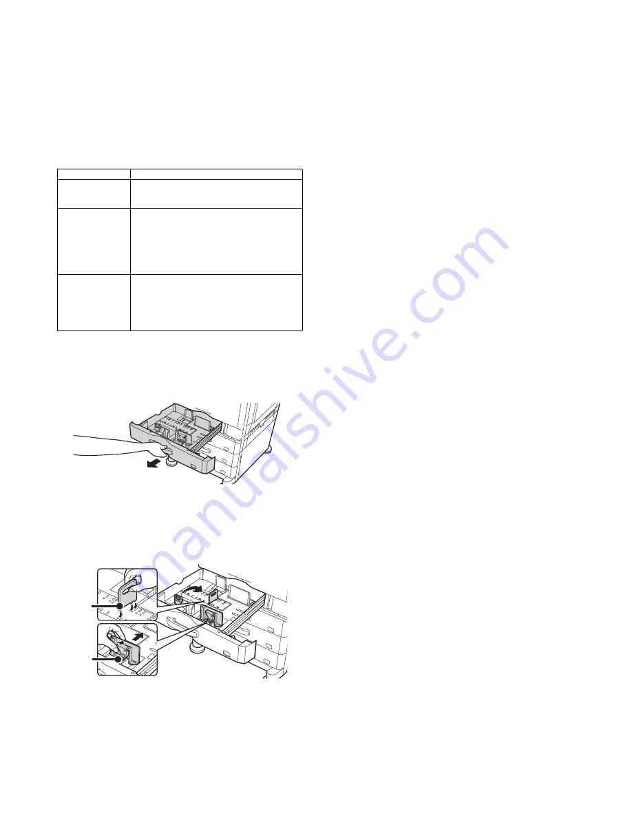
(2) Tray size setup

1)

Pull out the paper tray.
Gently pull the tray out until it stops.
If paper remains in the tray, remove it.

2)

Adjust the guide plates A and B by squeezing their lock levers
and sliding them to match the vertical and horizontal dimen-
sions of the paper to be loaded.
The guide plates A and B are slidable. Slide each guide plate
while squeezing its lock lever.

Item

Description

Type

Select the type of paper that is loaded in the tray. 
The paper types that can be selected vary by paper 
tray.

Size

Select the paper size from the list. The paper sizes 
that can be selected vary by tray. The sizes that 
can be selected may also be restricted by the paper 
type selected above. 
If the desired size does not appear in the list, select 
[Custom Size] and directly enter the size (only for 
the bypass tray).

Feeding Approved 
Job

Select the modes that can be used. If there is a 
function that you do not wish to be used with the 
selected tray, disable the function. When the "Type" 
is other than plain paper, recycled paper, colored 
paper, or a user type, [Fax] and [Internet Fax] 
cannot be selected.

A

B

Summary of Contents for MX-M264N

Page 1: ...TR11 JOB SEPARATOR 9 1 10 MX PB15 PRINTER EXPANSION KIT 10 1 11 MX PK11 PS3 EXPANSION KIT 11 1 12 MX PF10 BARCODE FONT KIT 12 1 13 MX NSX1 NETWORK SCANNER EXPANSION KIT 13 1 14 MX FX11 FACSIMILE EXPANSION KIT 14 1 15 MX FWX1 INTERNET FAX EXPANSION KIT 15 1 16 AR SU1 STAMP UNIT 16 1 17 MX FR37U DATA SECURITY KIT 17 1 18 MX AMX1 APPLICATION INTEGRATION MODULE 18 1 19 MX AMX2 APPLICATION COMMUNICATIO...

Page 2: ...11 FACSIMILE EXPANSION KIT 1 Unpacking 14 1 2 Installation 14 1 15 MX FWX1 INTERNET FAX EXPANSION KIT 1 Unpacking 15 1 2 Installation 15 1 16 AR SU1 STAMP UNIT 1 Unpacking 16 1 2 Installation 16 1 17 MX FR37U DATA SECURITY KIT 1 Unpacking 17 1 2 Installation 17 1 18 MX AMX1 APPLICATION INTEGRATION MODULE 1 Unpacking 18 1 2 Installation 18 1 19 MX AMX2 APPLICATION COMMUNICATION MODULE 1 Unpacking 1...

Page 3: ... to scratch NO SCRATCH NO LIGHT Be careful not to expose to light such as the photoconductor and the test chart NO SOLVENT Be careful not to use a solvent in cleaning etc NO DISASSEMLE Do not disassemble Not serviceable Example CCD unit OK GOOD Indicates a correct procedure or result in an adjustment etc NO GOOD Indicates a wrong procedure or result in an adjustment etc NOTE Indicates a note IMPOR...

Page 4: ...icates that a harness is secured Remove a clamp Attach a clamp Release a hook Indicates that a hook is released Fix a hook Indicates that a hook is fixed Disengage the pawl Symbol Meaning Work content Engage the pawl Screw lock Indicates that a screw is secured with adhesive Unlock Turn OFF the power Disconnect the power plug Symbol Meaning Kinds of parts Maintenance part Indicates a part which is...

Page 5: ...An electrical work is required Use of a step up transformer is also available In this case the capacity must be great enough for the max power consumption of the machine 3 Power frequency waveform The frequency must be within the range of the specified frequency 2 If power waveform is deformed a trouble may occur 4 Safety Be sure to properly ground the machine Grounding earth connection must be pe...

Page 6: ...s Copy quality may be adversely affected and a trouble may be caused 5 Vibration Avoid installation near a machine which produces vibrations If vibrations are applied to the copier machine copy images may be deflected and a trouble may be caused F Note for handling PWB and electronic parts When handling the PWB and the electronic parts be sure to observe the following precautions in order to preve...

Page 7: ... fingerprints oil grease or other foreign material on the fusing roller If these items are neglected a trouble may be generated in the copy and print image quality 2 Transit and delivery A Implements facility and manpower It is recommendable to use a forklift for bringing in the machine for safety If no forklift is available man power of two persons is required The machine is considerably heavy an...

Page 8: ... SCANNER EXPANSION KIT MX HD12 HARD DISK EXPANSION KIT MX US50 SHARPDESK 50 LICENSE KIT MX UN1HA Sharp OSA Network Scanner Tool 100 License Kit MX KB14 KEYBOARD MX USX1 SHARPDESK 1 LICENSE KIT MX USX5 SHARPDESK 5 LICENSE KIT MX US10 SHARPDESK 10 LICENSE KIT MX USA0 SHARPDESK 100 LICENSE KIT MX AMX1 APPLICATION INTEGRATION MODULE MX AMX2 APPLICATION COMMUNICATION MODULE MX AMX3 EXTERNAL ACCOUNT MOD...

Page 9: ...CODE FONT KIT OPT OPT 4 Image send expansion MX NSX1 NETWORK SCANNER EXPANSION KIT OPT STD MX FX11 FACSIMILE EXPANSION KIT OPT OPT MX FWX1 INTERNET FAX EXPANSION KIT OPT OPT 5 AR SU1 STAMP UNIT OPT OPT Authentication Security MX FR37U DATA SECURITY KIT OPT OPT 5 Application Solution MX USX1 SHARPDESK 1 LICENSE KIT OPT OPT MX USX5 SHARPDESK 5 LICENSE KIT OPT OPT MX US10 SHARPDESK 10 LICENSE KIT OPT...

Page 10: ...ed items check D Lock release 1 Tray rotation plate lock release 1 Pull out the tray Turn the fixing material and remove it Remove the caution label Attach the removed fixing material to the position shown in the figure for future use Close the tray which was pulled out 2 Scanner 2 3 mirror unit lock release 1 Remove the optical unit fixing screw and remove the note label No Name Quantity 1 Operat...

Page 11: ...d with the toner cartridge installed the EE EL error or an overtoner trouble may occur 1 With the front cabinet open connect the power plug to the power outlet 2 Turn ON the main power switch of the machine and the power switch on the operation panel 3 Enter the SIM25 2 mode 4 Close the front cabinet 5 After the machine completes cycling exit the simulation mode 6 Confirm that Install the toner ca...

Page 12: ... lock levers and sliding them to match the vertical and horizontal dimen sions of the paper to be loaded The guide plates A and B are slidable Slide each guide plate while squeezing its lock lever Item Description Type Select the type of paper that is loaded in the tray The paper types that can be selected vary by paper tray Size Select the paper size from the list The paper sizes that can be sele...

Page 13: ...the operation panel does not light up or blink when per forming installation A SPF glass unit attachment 1 Remove the right glass holder Remove the table glass and left glass holder 2 Attach the SPF glass unit included in the package Attach the table glass and right glass holder B RSPF unit attachment 1 Attach the RSPF unit to the main unit 2 Remove the rear upper cabinet cover 3 Connect the conne...

Page 14: ...n be sure to turn both the operation and main power switches off and disconnect the power plug from the power outlet Make double sure that the data lamp on the operation panel does not light up or blink when per forming installation A Document cover unit attachment 1 Attach the document cover unit to the main unit No Name Quantity 1 Document cover unit 1 1 ...

Page 15: ...he outlet A Remove the rear cover from the copier 1 Remove the two screws and then remove the rear cover from the copier B Remove the rear cover from the optional paper feed unit 1 Remove the two screws and then remove the rear cover from the optional paper feed unit C Remove the connector cover 1 Remove the cover from the connector MX DE17 MX DE18 Fixing plates 4 pcs Paper size label Screws M4 x ...

Page 16: ...ontained in the optional paper feed unit to the paper feed unit interface PWB For two tray type For one tray type F Attach the rear covers of the copier and the optional paper feed unit 1 Attach the rear covers of the copier and the optional paper feed unit using two screws respectively Right of rear side Screws M4 x 12 Detailed view Front side Screws M4 x 12 Screws M4 x 12 Fixing plate Fixing pla...

Page 17: ... plate to the specified size position Insert the power plug of the copier to the outlet and turn on the main switch of the copier Then carry out the following proce dure I Load paper into the paper tray 1 Do not exceed the maximum height line J Check for center displacement Set an original on the document glass and copy it using the paper tray in the copier Then copy an original using the attached...

Page 18: ...e adjuster covers 2 pcs as shown in the figure below and attach them Then close the door 3 Remove the paper tray Pull out the paper feed unit tray from the copier until it stops Lift it and remove it from the copier Machine stand Packed parts add MX DS16 MX DS17 Front adjusters 2 pcs Adjuster covers 2 pcs Copier connecting fixtures 2 pcs Screws S tight 2 pcs Screws P tight 4 pcs 110 Front adjuster...

Page 19: ...wo screws and remove the rear cover 7 Connect the copier or the paper feed unit and the desk with two screws P tight and two screws S tight packed together with the copier When connecting be careful of the direction of the connecting fixture of the copier 8 Attach the rear cover and fix it with the two screws 9 Install the paper tray Install the paper tray to the original position ུఘ Positioning p...

Page 20: ...remove the power plug of the machine from the outlet 1 Open the front cover 2 Remove the screws and remove the left cabinet 3 Remove the screw which are fixing the paper exit tray Remove the paper exit tray by using care for the tray paper presence detection harness which is connected to the back side of the paper exit tray FIN connection unit FIN front cover Second paper exit unit Paper holding a...

Page 21: ...l feed tray and the right door Remove the two screws and remove the right cabinet 9 Pass the harness packed together with the unit of the second paper exit unit though inside of the frame plate as shown in the figure Install the second paper exit unit to the machine and fix it with the four M4 S tight screws which are packed together with the finisher Connect the connector of the harness 10 Instal...

Page 22: ...emporarily 14 Slide the rail under the connection unit to the lock position 15 Engage the finisher connection plate with the notch in the stay at the right bottom of the machine Slide the connection plate to the bottom and attach M3 screw as shown Use the screw bundled to the package MEMO Press the right side of the connection plate 16 After attaching the screw pull the connection plate toward you...

Page 23: ...21 Install the finisher front cabinet lower with screw First attach the A screw A M3 round head screw Use the screw which was removed from the FIN connection unit B M4 P tight screw Use the screws which were removed from the paper exit tray of the machine 22 Install the left cabinet to the original position 23 Install the finisher front cover from the left side by sliding and fix the center of the...

Page 24: ... FN23 FINISHER 7 5 26 Connect the machine connection connector Non LPS Do not connect to devices other than specified peripheral devices of our company 27 Attach the staple position label to the document feed unit ...

Page 25: ...arness of the right paper exit unit to the hole of the second paper exit NOTE Wire the harness to the upper of the rib If wiring it to the under of the rib the harness may come into contact with the gear 5 Insert the pawl of the right paper exit unit to the oval hole of the frame of the main unit Insert the positioning boss of the main unit to the round hole in lower side 6 When tightening the scr...

Page 26: ...ght paper exit actuator and the paper holding arm 10 Remove the screw and remove the paper exit fan connector sheet 11 Install the harness cover OP and tightening the screw Paper holding arm Right paper exit actuator Insertion direction Right paper exit paper full detection fulcrum Insert it to the hole of the paper exit right cover R side F side ...

Page 27: ...t lever cover Dispose of the part after installation M4 x 12 P tight 3 Remove the right cabinet AS M4 x 10 P tight 2pcs 4 Install the second paper exit UN M4 x 10 S tight 4pcs 5 Connect the second paper exit UN connector to MCU UN Fixation treatment of the harness is required 6 Disengage the pawls in the sequence of 1 and 2 and remove the paper exit dummy cover Job separator unit Second paper exit...

Page 28: ...r tray AS 10 Install the rail dummy cover part to the guide rail so that slide the over part from front side to rear side After that insert the rib of tray part to the location of insertion of the second paper exit tray holder Check that it is caught while being pushing up the tray 11 Install the right cabinet AS M4 x 10 P tight 2pcs 12 Install the rear cabinet 13 Job separator setting in simulati...

Page 29: ... product key input mode c Enter the product key d Press the registration key 2 After completion of the product key input turn OFF the power switch on the operation panel of the machine and turn OFF the main power switch 3 Turn ON the main power switch and the power switch on the operation panel B Confirmation of function enable Execute SIM22 10 Machine configuration display to check to con firm th...

Page 30: ...ting mode b The machine enters the product key input mode c Enter the product key d Press the registration key 2 After completion of the product key input turn OFF the power switch on the operation panel of the machine and turn OFF the main power switch 3 Turn ON the main power switch and the power switch on the operation panel B Confirmation of function enable Execute SIM22 10 Machine configurati...

Page 31: ... operation panel B Confirmation of function enable Execute SIM22 10 Machine configuration display to check to con firm that the set functions are enable No Name Quantity 1 CD ROM 1 2 Product key sheet 1 Font No Font name 1 Code128TT Regular 2 Code128 NarrowTT Regular 3 Code128 WideTT Regular 4 Code39HalfInch Regular 5 Code39OneInch Regular 6 Code39QuarterInch Regular 7 Code39SmallHigh Regular 8 Co...

Page 32: ...ters the product key input mode c Enter the product key d Press the registration key 2 After completion of the product key input turn OFF the power switch on the operation panel of the machine and turn OFF the main power switch 3 Turn ON the main power switch and the power switch on the operation panel B Confirmation of function enable Execute SIM22 10 Machine configuration display to check to con...

Page 33: ...ming installation A Rear cabinet and left cabinet removal 1 Remove the rear cabinet 2 Remove the left cabinet B I F cable connection 1 Pass the I F cable through the hole in the frame to connect to the connector Fix the binding band and FG line Taiwan Brazil South Africa with the M3 screw included in the package NOTE Check to confirm that it is securely connected Except Taiwan Brazil South Africa ...

Page 34: ...setting of the machine matches the specifications of the FAX destination If not the FAX may not function properly G Clear the FAX related software swithes 1 Enter the SIM66 2 mode 2 Press DEST CODE button 3 Take a note of the corresponding destination code 4 Press BACK button to return to the code entry mode 5 Enter the destination code taken in procedure 3 and press SET button 6 Press EXECUTE and...

Page 35: ...ble setting of functions 1 Enter the product key to enable the functions a Enter the system setting mode b The machine enters the product key input mode c Enter the product key d Press the registration key 2 After completion of the product key input turn OFF the power switch on the operation panel of the machine and turn OFF the main power switch 3 Turn ON the main power switch and the power switc...

Page 36: ...double sure that the data lamp on the operation panel does not light up or blink when per forming installation A RSPF unit removal 1 Remove the rear upper cabinet cover Remove the earth wire and disconnect the connector 2 Remove the RSPF unit from the main unit 3 Put the RSPF unit on a stable table with the OC mat upside B Stamp unit attachment 1 Open the OC mat 2 Remove the sensor cover 3 Remove ...

Page 37: ...cabinet cover D Finish stamp cartridge attachment 1 Open the left cover and open the document tray 2 Attach the finish stamp cartridge E Turn ON the power of the main unit 1 Connect the power plug of the machine to the power outlet and turn ON the main power switch and the operation panel power switch F Installation check 1 Use SIM22 10 to check to confirm that the finish stamp AR SU1 is recognize...

Page 38: ... or blinking data that has not been processed remains in the memory of the main unit including HDD Output or trans mit all the data to clear the data remaining in the main unit and then start installation NOTE Before installation be sure to turn both the operation and main power switches off and disconnect the power plug from the power outlet Make double sure that the data lamp on the operation pa...

Page 39: ...1 Enter the product key to enable the functions a Enter the system setting mode b The machine enters the product key input mode c Enter the product key d Press the registration key 2 After completion of the product key input turn OFF the power switch on the operation panel of the machine and turn OFF the main power switch 3 Turn ON the main power switch and the power switch on the operation panel ...

Page 40: ...ode c Enter the product key d Press the registration key 2 After completion of the product key input turn OFF the power switch on the operation panel of the machine and turn OFF the main power switch 3 Turn ON the main power switch and the power switch on the operation panel B Confirmation of function enable Execute SIM22 10 Machine configuration display to check to con firm that the set functions...

Page 41: ... enters the product key input mode c Enter the product key d Press the registration key 2 After completion of the product key input turn OFF the power switch on the operation panel of the machine and turn OFF the main power switch 3 Turn ON the main power switch and the power switch on the operation panel B Confirmation of function enable Execute SIM22 10 Machine configuration display to check to ...

Page 42: ...he product key input mode c Enter the product key d Press the registration key 2 After completion of the product key input turn OFF the power switch on the operation panel of the machine and turn OFF the main power switch 3 Turn ON the main power switch and the power switch on the operation panel B Confirmation of function enable Execute SIM22 10 Machine configuration display to check to con firm ...

Page 43: ...tion to backup the address book data 3 When the home screen of the operation panel has been cus tomized use the device cloning function to backup the SD card data NOTE The backup data must be restored to the machine after installing an option HDD Refer to the page of 4 User data restore 4 If there are some FAX IFAX image data use SIM66 62 to backup the image data into a USB memory Then give the PD...

Page 44: ...lace the SD card 1 Connect the power plug of the machine to the power outlet and turn ON the main power switch and the operation panel power switch 2 Backup the SIM adjustment data in the SD card into the HDD Enter the SIM56 11 mode and press EXECUTE key and YES key When the backup operation is completed COMPLETE is dis played Check to confirm the display 3 Turn OFF the operation panel power switc...

Page 45: ...e 2 Attach the rear cabinet 4 User data restore NOTE When the user data were backed up in the procedure 2 the user data must be restored When a HDD option is installed to a machine which has been not used the procedure is not required 1 Use SIM56 2 to restore the data which has been backed up in the procedure 2 1 Insert the USB memory into the USB connector in the machine operation section Enter t...

Page 46: ...ternal fixture removal 1 Remove the front cabinet upper 2 Remove the operation panel base plate 3 Remove the operation panel base plate B from the operation panel base plate A MEMO When attaching the keyboard the operation panel base plate B is not used B Operation panel removal 1 Remove the operation panel unit C Keyboard unit attachment 1 Attach the keyboard unit mounting plate and fix it with t...

Page 47: ...late 2 Attach the front cabinet upper F Turn ON the power of the main unit 1 Connect the power plug of the machine to the power outlet and turn ON the main power switch and the operation panel power switch G Keyboard input check 1 Touch Image send on the touch panel 2 Touch File name on the touch panel 3 Push the keyboard and check the input display on the touch panel H USB operation check 1 Inser...

Page 48: ...ot used 6 Clamp LHLDW2037FCPZ 1 Not used 7 Screw XBPS730P08KS0 1 Not used DH POWER 1 3 2 4 7 5 6 Kit name Kit code No Part name Part code Q ty Remarks Scanner heater kit DKIT 0427FC11 120V series DKIT 0427FC12 230V series 1 Scanner heater 120V RHETP0129FCPZ 1 Scanner heater 230V RHETP0130FCPZ 2 Heater fixing plate LPLTM6923FCZZ 1 3 Banding band LBNDJ0013FCZ1 2 4 Clamp LHLDW7011XCZZ 5 5 Screw M3 x ...

Page 49: ...et 2 Remove the left cabinet 3 Remove the paper exit tray 2 WH PWB attachment 1 Attach the supporter and attach the WH PWB 2 Connect the harnesses bundled with an omega clamp to the WH PWB according to the connector shapes and colors NOTE Connectors CN3 and CN4 can be used commonly 3 Dehumidifier heater control switch attachment 1 Connect the WH harness to the dehumidifier heater control switch an...

Page 50: ...re the marking position on the harness of the scanner heater to the heater fixing plate with the banding band 2 Extend the harness and secure the other position of it with banding band 3 Tighten the snap band and cut its tip to approx 5 mm or less Slide the banding band head to the square hole Part that is enclosed by the mark NOTE The banding band head and cut tip must not protrude behind the hea...

Page 51: ...w M3 x 4 Round tipped 4 Attach the scanner heater and secure it with the screw M4 x 6 Bind machine screw Pass the harness through the clamp NOTE The convex part of the scanner heater must be inserted into the hole of the scanner frame 5 Tighten the loose scanner heater harness by pulling it in the arrow direction and secure it with the snap band then cut its tip to approx 5 mm or less 6 Move the l...

Page 52: ...nd fix it with screws C Operation check after installation 1 Turn on the dehumidifier heater switch 2 Measure the resistance value between the earth terminal and the AC terminal L side and between the earth terminal and AC terminal N side with the circuit tester and confirm they are not short circuited 3 When not using the dehumidifier heater after checking turn off the dehumidifier heater switch ...

Page 53: ... the front cabinet upper 2 Remove the operation panel base plate 3 Remove the operation panel unit No Manufacturer Model Name 1 RFIDeas RDR 6081AKU 2 Equitrac Y591 EHID 201 v01 3 Elatec TWN3 4 RFIDeas RDR 7582AKU No Parts code Parts name Price rank Q ty 1 LHLDZ0171QSZZ IC Card reader holder B 1 2 LHLDZ0172QSZZ IC card reader holder C 1 3 PTEP 0325FCZZ Card reader fixing tape Double stick tape AP 2...

Page 54: ...n Fit with the notch and the lower edge Holder type C Y591 EHID 201 v01 Vertical and horizontal directions Fit with the notches 2 Cut out the boss Holder type B RDR 6081AKU RDR 7582AKU NOTE Don t cut the boss in case of TWN3 installation 3 Attach the IC card reader to the IC card reader holder accord ing to the attachment reference ribs NOTE The attachment reference position differs depending on t...

Page 55: ...ns Adjust the bind length of card reader cable and bind up it with banding band Fix the banding band by inserting the lock part of it into the hole in the frame Connect the USB mini harness to the card reader cable C Attach the operation panel D Connect the connector of the IC card reader to the connector of the machine E Turn ON the power of the main unit 1 Connect the power plug of the machine t...

Page 56: ...ttach the operation panel base plate 2 Attach the front cabinet upper I Making and importing of the setting file for HID card reading NOTE The following procedures are executed only when a request is made by a user for customizing the data format of IC card reading 1 Make the setting file for HID card reading For the making procedures refer to the Manual of Setting File for HID Card Reading 2 Copy...

Page 57: ...n 3 Length 5 Decoded Data abcde Example 2 Specification by delimiter Start Delimiter End Delimiter Decoded Data 12345 When Decoded Data 12345 Example Pre Post abc Padded Data 12345abc Section name Description General Setting of the general information General Key name Description Version Setting file version Fixed to 1 0 Card Set as shown below depending on the kind of the card to be set 1 Key val...

Page 58: ... is successfully completed the result is indi cated as shown above with the user information Check to con firm that the displayed items are proper If not check the improper item HID setting file template The extension of ini should be added Details of error Error display Error content and remedy Card is not found Content Card is not found Remedy Check to confirm that the card is securely set in th...

Page 59: ...ance to use the remote operation panel function Let the user make the password and use SIM26 78 to set it MEMO After installation of an option upgrade all the firmware s to the latest versions 2 Remote operation panel function password setting procedures 1 Enter the SIM26 78 mode 2 Enter the password with 10 key Within 5 8 digits The entered password is displayed on the column of NEW To modify the...

Page 60: ...heck item list Equipped condition Key in operation panel Display operation panel Paper feed operation Hand feed Main unit paper tray Desk unit paper feed tray With the desk unit installed Paper size detection Originals size detection Original table mode RSPF mode RSPF operation two sided copy S S mode D S mode S D mode D D mode Bookbinding operation When the finisher is installed Stapling operatio...

Page 61: ...ng Print the various setup data and the adjustment data list with SIM22 6 and keep the data In case of a memory trouble if the data are not kept all the adjustments must be made again If the data are kept the setup values and the adjustment values can be entered without adjustments shortening the servicing time ...

Page 62: ...machine 1 Remove the following consumable parts from the machine Paper Toner cartridges Development cartridge 2 Lock the following sections Scanner Optical section Paper cassette lift plate NOTE Since the hard disk drive is built in the machine use care not to exert vibrations or shocks to the machine when in transit ...

Page 63: ...free solder is about 220 C which is about 40 C higher than that of conventional lead solder and its soldering capacity is inferior to conventional one it is apt to keep the soldering iron in contact with the PWB for longer time This may cause land separation or may exceed the heat resistive temperature of components Use enough care to separate the soldering iron from the PWB when completion of sol...

Page 64: ...sfara vid felaktigt batteribyte Använd samma batterityp eller en ekvivalent typ som rekommenderas av apparattillverkaren Kassera använt batteri enligt fabrikantens instruktion German Achtung Explosionsgefahr bei Verwendung inkorrekter Batterien Als Ersatzbatterien dürfen nur Batterien vom gleichen Typ oder vom Hersteller empfohlene Batterien verwendet werden Entsorgung der gebrauchten Batterien nu...

Page 65: ...003 Windows Server 2008 and Internet Explorer are registered trademarks or trademarks of Microsoft Corporation in the U S A and other countries PostScript is a registered trademark of Adobe Systems Incorporated Macintosh Mac OS AppleTalk EtherTalk Laser Writer and Safari are registered trademarks or trademarks of Apple Inc IBM PC AT and Power PC are trademarks of International Business Machines Co...

Reviews: