


MX-M1204 MX-M904/M1054/M1204 (MAIN UNIT) 2 – 17
7)
Select [FACTORY] target, and press [EXECUTE] key.
When the gray balance is customized with the manual gray
balance adjustment (SIM 67-25) according to the user's
request and the gray balance is registered as the service tar-
get with SIM 67-27, if the gray balance is adjusted to that gray
balance, select the [SERVICE] target.
The printer gray balance adjustment (step 1) is automatically
performed and the gray balance check patch image is printed
out.
If there is any streak or unclear print on the printed check pat-
tern, check the print engine for any problems.
8)
The initial setting menu of the halftone image correction is dis-
played.
Press [OK] key.
The initial setting of the halftone image correction is per-
formed.
9)
Wait until [EXECUTE] key is displayed.
When it is displayed, press it.
The halftone image correction is performed.
10) When "COMPLETED THIS PROCEDURE" is displayed, the
adjustment operation is completed.
Cancel SIM46-74.
NOTE:
The adjustment result becomes valid only when the
both adjustments in the copy mode and in the printer
mode are completed.
For example, if the copy gray balance adjustment
(automatic adjustment) is performed and the simula-
tion is canceled, the adjustment result is invalid.
11) Check the copy gray balance and density.
(Refer to the item of the copy gray balance and density check.)
When the gray balance and the density are unsatisfactory after
the automatic adjustment by selecting the factory target in pro-
cedure 4), execute the manual gray balance adjustment
(ADJ11C (2)).
Also when the service target is selected in procedure 4) to exe-
cute the automatic adjustment and a satisfactory result is not
obtained, perform the manual gray balance adjustment (ADJ
11C (2)).
12) Check the printer gray balance and density.
(Refer to the item of the printer gray balance and density
check.)
If a satisfactory result on the gray balance and the density is
not obtained with the automatic adjustment, execute the man-
ual adjustment (SIM 67-25) (ADJ 11E (2)).
Also when the service target is selected in procedure 7) to exe-
cute the automatic adjustment and a satisfactory result is not
obtained, perform the manual gray balance adjustment (ADJ
11E (2)).
If the gray balance or density is not in the satisfactory level
even after execution of the automatic and manual adjustments,
there may be another cause.
Troubleshoot the cause, repair or perform necessary works,
and repeat the adjustment from the beginning.
M. Function and operation check
Check that the following operations are normal.
N. Setup and adjustment data recording
Print the various setup data and the adjustment data (list) with
SIM22-6 and keep the data.
• In case of a memory problems, if the data is not kept, all the
adjustments must be made again.
• If the data is kept, the setup values and the adjustment values
can be entered without adjustments, shortening the servicing
time.
Q
O P
N
M
L
K
J
I
H
G
F
E
D
C
B
A
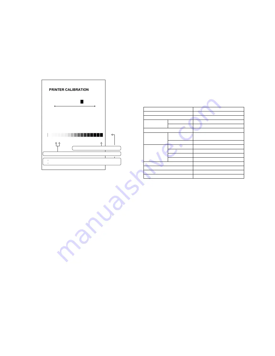
Bk
1) The max. density section is not blurred.
2) Patch C or D is very slightly copied.
3)
The patch density is identical between patches or not reversed.
The patch density is changed gradually.
High density
Low density
Check item list
Equipped condition
Key-in (operation panel)
Display (operation panel)
Paper feed
operation
Hand feed
Paper tray
Paper size detection
Originals size
detection
Original table
mode
DSPF mode
DSPF
operation/
duplex
operation
S-S mode
D-S mode
S-D mode
D-D mode
Bookbinding operation
When the finisher is installed
Stapling operation
When the finisher is installed
Grouping operation
When the finisher is installed
Sorting operation
When the finisher is installed