Sharp MX-M1054 Installation Manual Download Page 11

MX-M1204  MX-M904/M1054/M1204 (MAIN UNIT)  2 – 10

(1)

Turn ON the power of the main unit

1)

Connect  the  power  plug  of  the  machine  to  the  power  outlet,
and  turn  ON  the  main  power  switch  and  the  operation  panel
power switch.

(2)

Keyboard input check

1)

Touch [E-Mail] on the touch panel.

2)

Touch the input column of the address.

3)

Input the address with the keyboard, and check the input result
on the touch panel.

(3)

USB operation check

1)

Insert the USB memory into the USB connector of the opera-
tion panel.

2)

Check to confirm that the recognition mark of the USB memory
is displayed on the operation panel.

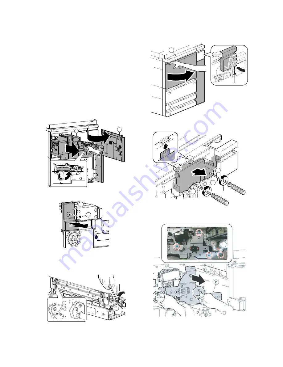
E. Fusing heat roller pressure

1)

Open  the  front  cover  (a),  and  pull  out  the  intermediate  frame
(b).

2)

Remove the screw (a), and remove the cover (b).

3)

Insert a screwdriver into the pressure release shaft (a) to apply
pressure.

* When  the  pressure  is  released,  the  arrow  on  the  pressure

release  shaft  faces  diagonally  (b).  When  the  pressure  is
applied, the arrow faces upward (c).

NOTE:

If  the  machine  is  left  unused  for  one  month  or  more,  the
heat  roller  rubber  may  be  deformed.  In  such  a  case,
release the pressure.

F. Developer supply

1)

Open  the  front  cover  (a),  and  pull  out  the  intermediate  frame
(b).

2)

Remove the screw (a), and remove the cover (b).

3)

Remove the blue screw, and remove the plate (b).

4)

Slide the developing unit (a) to the right, and pull it out until the
grip (b) can be held.

a

b

a

b

a

c

b

a

b

a

a

b

Summary of Contents for MX-M1054

Page 1: ...ts with specified ones for maintaining the safety and performance of the set This document has been published to be used for after sales service only The contents are subject to change without notice SHARP CORPORATION INSTALLATION MANUAL MX M904 MX M1054 MX M1204 DIGITAL MULTIFUNCTIONAL SYSTEM MODEL ...

Page 2: ...l ure of the PWB B Warning for servicing 1 Be sure to only connect the power cord to an outlet that meets the specified voltage and current requirements Avoid complex wiring which may lead to a fire or an electric shock It may cause a fire or an electric shock 2 If there is any abnormality such as a smoke or an abnormal smell interrupt the job and disconnect the power cord It may cause a fire or a...

Page 3: ...arts may become deformed discolored or undergo qualitative change It may cause a breakdown or copy quality problems 5 Place which is full of organic gases such as ammonium The organic photoconductor OPC drum used in the machine may undergo qualitative change due to organic gases such as ammonium Installation of this machine near a diazo type copier may result in copy quality problems 6 Place of ex...

Page 4: ...material attached If the machine is delivered without the fix ing material the drum may be scratched NOTE For USA CANADA If the fusing performance is insufficient in a special environment such as low temperature and low humidity an environment that heavy paper is mainly used and so on when 208V power supply is used please replace with 208V lamp RLMPU0764FCPZ Measurement method Measure the voltage ...

Page 5: ...h enough to remove the bot tom pad R 5 Remove the vinyl bag from the main unit 6 Remove the slope Slope Order from parts 7 Insert the ramps in the cut outs in the skid 8 Cut the part of the bottom case that overlaps with slope 9 Carefully roll the main unit down the ramps in the direction of the arrow Part name Part code Skid slope DKiT 0367FCZZ ...

Page 6: ...nt cover 3 Remove the protection sheet and the Operation Manual 4 Remove the screw a and remove the cover b 5 Remove the protection material Packing material for fixing the separation pawls NOTE When moving the machine again after unpacking be sure to attach the protection material If not the OPC drum may be damaged 6 Pull out the intermediate frame a a b ...

Page 7: ...ockwise the height is decreased When turned clockwise the height is increased Common to the options the height of which is adjusted by the adjuster bolt NOTE Lower the height of the MX CF11 to the lowest position before adjusts the level between the MX CF11 and the main body Adjust the height of the top surface of main body refer ence to the top surface of the MX CF11 B Lock release 1 Scanner 2 3 ...

Page 8: ...ve the blue screw c from the tray 3 only C Label attachment 1 Attach the document scan section label to the top of the DSPF unit D Installation of operation panel unit 1 Remove the operation panel upper cover with the screw 2 Attach the frame and fix the screw Packed items No 5 x4 3 Attach the four clamps Packed items No 6 x4 and arrange the wires NOTE When wiring the harness be sure to check that...

Page 9: ...items No 8 with the screw Packed items No 4 x2 NOTE At that time pass the harness through the hole in the cover NOTE Place the cover on the inside of plate 6 Bind up the harness with clamp as per the following picture NOTE Be careful not to pinch the harness If it is difficult to connect the connector remove the cabinet in the right side 7 Pass the harness through the clamp and the wire saddle and...

Page 10: ...ration Panel cover B Packed items No 2 with the screw Packed items No 4 x2 And attach the lower cover Packed items No 10 with the screw Packed items No 4 10 Attach the panel cover below Packed items No 3 with the screw Packed items No 4 11 Attach the operation panel upper cover with the screw ...

Page 11: ...n panel E Fusing heat roller pressure 1 Open the front cover a and pull out the intermediate frame b 2 Remove the screw a and remove the cover b 3 Insert a screwdriver into the pressure release shaft a to apply pressure When the pressure is released the arrow on the pressure release shaft faces diagonally b When the pressure is applied the arrow faces upward c NOTE If the machine is left unused fo...

Page 12: ...and place the developing unit down with the leg extended 6 Remove the connector a the screw b and the cover c Be careful not to smear the pin of the connector a with toner 7 Remove the screw a and remove the guide b 8 Remove the cover a 9 While rotating the coupling a supply developer b 10 Attach the cover a 11 Attach the guide a and secure it with the screw b a b b a a b c a a b a a b a ...

Page 13: ...g leg a under the developing unit and install the developing unit b When inserting a developing unit with SIM25 2 not exe cuted be sure to check that the power is turned OFF 14 Slide the developing unit a to the left and lock it 15 Attach the plate a and secure it with the screw b 16 Attach the cover a and secure it with the screw b 17 Insert the toner tray a and close the front cover b b b a c b ...

Page 14: ...e front cover and remove the toner cartridge Then enter the input of SIM25 2 5 After entering the simulation close the front cover a 6 Press EXECUTE button and the simulation is executed After stirring toner the toner density control sensor values are sampled to get the average value of the sensor detection level which is set saved as the reference toner density control value 7 After completion of...

Page 15: ...set the paper size 1 Press the SETTINGS key on the operation panel 2 Press the SYSTEM SETTINGS key 3 Touch the Paper Tray Settings key 4 Touch the Tray 3 key 5 Select recycled on the selection box of the Type Select A4 on the selection box of the Size Touch the Submit key 2 Tray size setup a Inch series tray 1 tray 2 LT to A4 1 Pull out the tray 1 2 a 2 Push down the paper feed base plate a gently...

Page 16: ...the 5 ADJUSTMENT on the Service Manual Check that the following items are within specification If not carry out the adjustment NOTE When installing the copier be sure to carry out the copy gray balance and the printer gray balance 1 Image loss void area see ADJ 9 2 Copy gray balance 11 A Auto adjustment 1 Enter the SIM 46 74 mode 2 Press EXECUTE button The high density process control is performed...

Page 17: ...matically and the adjustment pattern is printed If there is any streak or unclear print on the printed check pat tern check the print engine for any problems 5 Press EXECUTE key The printer gray patch image adjustment pattern is printed out A4 11 x 8 5 or A3 11 x 17 paper is automatically selected 6 Set the gray patch image adjustment pattern printed in the procedure 5 on the document table Set th...

Page 18: ...ay balance adjustment ADJ 11C 2 12 Check the printer gray balance and density Refer to the item of the printer gray balance and density check If a satisfactory result on the gray balance and the density is not obtained with the automatic adjustment execute the man ual adjustment SIM 67 25 ADJ 11E 2 Also when the service target is selected in procedure 7 to exe cute the automatic adjustment and a s...

Page 19: ...feed system option 2 Remove the following consumable parts from the machine Paper Toner cartridge Development cartridge 3 Lock the following sections Scanner Optical section Paper cassette lift plate 4 Attach the protection material to the position shown below Use the packing material for fixing the separation pawls which was removed when unpacking NOTE Since the hard disk drive is built in the ma...

Reviews: