background image

MX-C301  MX-C301/C301W(MAIN UNIT)  2 – 3

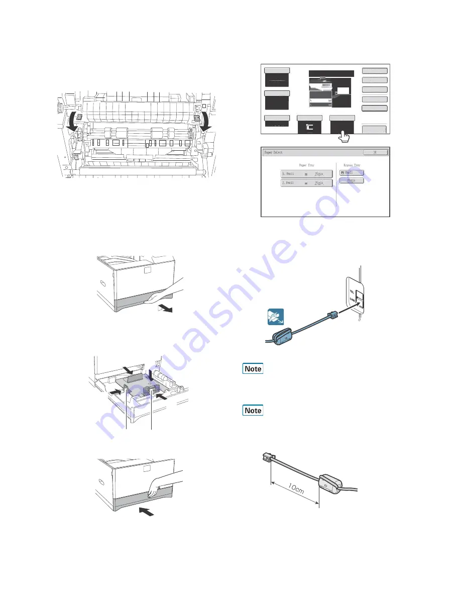
D. Fusing unit lever

1) Open the right door unit.. 

2) Turn the levers of the Fusing unit to add the pressure. 

* Only the levers can add or release the pressure. There is no
screw for adding or releasing the pressure. 

NOTE: When the machine is left for one month without using, the

Fusing heat roller could be deformed. If the machine is not
going to be used for an extended period, release the pres-
sure on the fusing rollers. 

E.Tray size setup

1) Gently  pull  out  the  tray  until  it  stops.  If  paper  is  in  the  tray,

remove it.

2) Adjust the guide plates A and B to the vertical size and the hori-

zontal size of paper. 

The guide plates A and B are movable. Hold the fixing knob to
slide the guide plates A and B to match the paper size.

3)

Insert the tray slowly.

4)

Touch  the  [Paper  Select]  key.     Then,  select  the  tray that  the
customer wants to use by touching the key of the desired tray.

F.Line  cable  connection  (Only  for  the  machine
with FAX)

1) Connect  the  telephone  line  to  the  modular  jack  indicated  as

“LINE.”

It is necessary to prepare the line cable by yourself. The telephone
cable does not come with the machine. 

When  connecting  the  line  cable  (to  LINE  or  TEL),  wind  the  line
cable two turns around the included ferrite core as shown in the fig-
ure, and connect to the modular jack which is marked with “LINE.”

(1)

(2)

(2)

(2)

Summary of Contents for MX-C301

Page 1: ...ts with specified ones for maintaining the safety and performance of the set This document has been published to be used for after sales service only The contents are subject to change without notice SHARP CORPORATION INSTALLATION MANUAL MX C301 C301W MODEL DIGITAL FULL COLOR MULTIFUNCTIONAL SYSTEM ...

Page 2: ... required Use of a step up transformer is also available In this case the capac ity must be great enough for the max power consumption of the machine 3 Power frequency waveform The frequency must be within the range of the specified frequency 2 If the power waveform is improper a problem may occur with the machine 4 Safety Be sure to properly ground the machine Grounding earth connection must be p...

Page 3: ...fusing and transfer unit handling When handling the OPC drum developing fusing units and transfer units observe the following items Drum unit To prevent damage to the OPC drum avoid working on the drum unit in high intensity light areas When the OPC drum is removed from the machine cover it with light blocking material When using paper use about 10 sheets of paper to cover it Be careful not to att...

Page 4: ...surface Be sure not to hold the scanner unit to lift up the main unit B Removal of the fixing tape and protection mate rial With only for north America model remove the warning sheet C Check the packed items 1 Check that all the parts are in the package 2 Installation A Remove the cap from developing unit 1 Remove the tray No Packed part names Quantity 1 Toner cartridge 1 piece for each color Othe...

Page 5: ...ately 1K A4 LT 5 1 Shake the toner cartridge included in package vertically sev eral times 2 Insert the toner cartridge horizontally and straight until it locks NOTE Be sure to install the color cartridges to their proper posi tions Avoid installation to a different color position NOTE Do not forcibly insert the toner cartridge Keep holding the cartridge and completely insert it NOTE When the mach...

Page 6: ...de plates A and B to the vertical size and the hori zontal size of paper The guide plates A and B are movable Hold the fixing knob to slide the guide plates A and B to match the paper size 3 Insert the tray slowly 4 Touch the Paper Select key Then select the tray that the customer wants to use by touching the key of the desired tray F Line cable connection Only for the machine with FAX 1 Connect t...

Page 7: ...ent result is dis played The current skew level for each color is displayed on the SKEW display section 3 Make test print in the simulation mode for checking whether the void off center and printing quality are correct If the test results are not correct refer to 5 ADJUSTMENT from the Service Manual and perform the adjustments Void SIM50 01 50 10 Printing position SIM50 10 Off center Registration ...

Reviews: