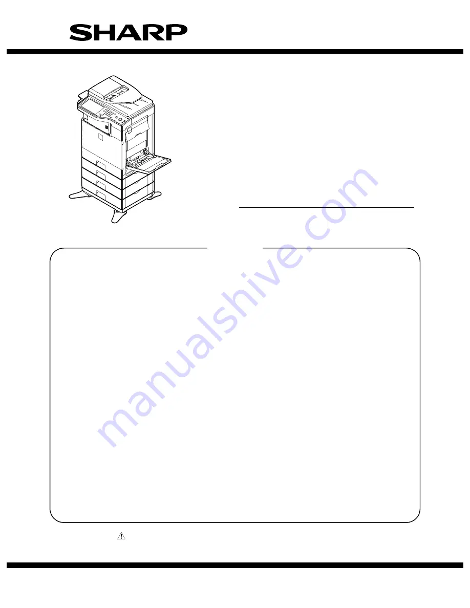
background image

INSTALLATION MANUAL

Parts marked with "

" are important for maintaining the safety of the set. Be sure to replace these parts with

specified ones for maintaining the safety and performance of the set.

This document has been published to be used
for after sales service only.
The contents are subject to change without notice.

SHARP CORPORATION

CONFIGURATION

[1]

MX-B381/B401 (MAIN UNIT) . . . . . . . . . . . . . . . . . . . . . . . . . . . . . . . . . . . . . . . . . . . . . 1-1

[2]

MX-CSX1/CSX2 (500-SHEET PAPER FEED UNIT) . . . . . . . . . . . . . . . . . . . . . . . . . . . 2-1

[3]

MX-FN12 (FINISHER) . . . . . . . . . . . . . . . . . . . . . . . . . . . . . . . . . . . . . . . . . . . . . . . . . . 3-1

[4]

MX-FXX3 (FACSIMILE EXPANSION KIT) . . . . . . . . . . . . . . . . . . . . . . . . . . . . . . . . . . . 4-1

[5]

AR-PF1 (BARCODE FONT KIT) . . . . . . . . . . . . . . . . . . . . . . . . . . . . . . . . . . . . . . . . . . 5-1

[6]

MX-FR16U (DATA SECURITY KIT). . . . . . . . . . . . . . . . . . . . . . . . . . . . . . . . . . . . . . . . 6-1

[7]

MX-FWX1 (INTERNET FAX EXPANSION KIT) . . . . . . . . . . . . . . . . . . . . . . . . . . . . . . . 7-1

[8]

MX-PUX1 (XPS EXPANSION KIT)  . . . . . . . . . . . . . . . . . . . . . . . . . . . . . . . . . . . . . . . . 8-1

[9]

MX-AMX1 (APPLICATION INTEGRATION MODULE)  . . . . . . . . . . . . . . . . . . . . . . . . . 9-1

[10] MX-AMX2 (APPLICATION COMMUNICATION MODULE) . . . . . . . . . . . . . . . . . . . . . 10-1

[11] MX-AMX3 (EXTERNAL ACCOUNT MODULE) . . . . . . . . . . . . . . . . . . . . . . . . . . . . . .  11-1

[12] MX-SMX3 (EXPANSION MEMORY BOARD) . . . . . . . . . . . . . . . . . . . . . . . . . . . . . . . 12-1

[13] DEHUMIDIFIER HEATER KIT (SERVICE PARTS) FOR THE MAIN UNIT . . . . . . . . . 13-1

[14] DEHUMIDIFIER HEATER KIT (SERVICE PARTS) FOR THE MX-CSX1/CSX2 . . . . .  14-1

TopPage

CODE: 00ZMXB401/I2E

MX-B381

MX-B401

MODEL

DIGITAL MULTIFUNCTIONAL 

SYSTEM

CONTENTS

Summary of Contents for MX-B381

Page 1: ...PER FEED UNIT 2 1 3 MX FN12 FINISHER 3 1 4 MX FXX3 FACSIMILE EXPANSION KIT 4 1 5 AR PF1 BARCODE FONT KIT 5 1 6 MX FR16U DATA SECURITY KIT 6 1 7 MX FWX1 INTERNET FAX EXPANSION KIT 7 1 8 MX PUX1 XPS EXPANSION KIT 8 1 9 MX AMX1 APPLICATION INTEGRATION MODULE 9 1 10 MX AMX2 APPLICATION COMMUNICATION MODULE 10 1 11 MX AMX3 EXTERNAL ACCOUNT MODULE 11 1 12 MX SMX3 EXPANSION MEMORY BOARD 12 1 13 DEHUMIDIF...

Page 2: ...g 6 1 2 Installation 6 1 7 MX FWX1 INTERNET FAX EXPANSION KIT 1 Unpacking 7 1 2 Installation 7 1 8 MX PUX1 XPS EXPANSION KIT 1 Unpacking 8 1 2 Installation 8 1 9 MX AMX1 APPLICATION INTEGRATION MODULE 1 Unpacking 9 1 2 Installation 9 1 10 MX AMX2 APPLICATION COMMUNICATION MODULE 1 Unpacking 10 1 2 Installation 10 1 11 MX AMX3 EXTERNAL ACCOUNT MODULE 1 Unpacking 11 1 2 Installation 11 1 12 MX SMX3 ...

Page 3: ...2 Finisher MX CSX2 500 sheet paper feed unit AR PF1 Bar code font kit MX FWX1 Internet fax expansion kit MX PUX1 XPS expansion kit MX USX1 Sharpdesk 1 license kit MX AMX1 Application integration module MX AMX2 Application communication module MX AMX3 External account module MX FXX3 Facsimile expansion kit MX SMX3 Expansion memory board MX USX5 Sharpdesk 5 license kit MX US10 Sharpdesk 10 license k...

Page 4: ...duct key target Paper feed system 500 sheet paper feed unit MX CSX1 OPT 500 sheet paper feed unit MX CSX2 OPT Business card feeder MX BTX1 OPT Paper exit system Finisher MX FN12 OPT Electrical system ROM Bar code font kit AR PF1 OPT Data security kit MX FR16U OPT Yes Electrical system Software Internet fax expansion kit MX FWX1 OPT Yes XPS expansion kit MX PUX1 OPT 1 Yes Sharpdesk 1 license kit MX...

Page 5: ...le In this case the capacity must be great enough for the max power consumption of the machine 3 Power frequency waveform The frequency must be within the range of the specified frequency 2 If power waveform is deformed a trouble may occur 4 Safety Be sure to properly ground the machine Grounding earth connection must be performed before inserting the power plug into the power outlet When disconne...

Page 6: ...and a trouble may be caused 2 Transit and delivery A Implements facility and manpower It is recommendable to use a forklift for bringing in the machine for safety If no forklift is available man power of two persons is required The machine is considerably heavy and requires safety precautions for delivery and installation Transit of the machine must be made in packed condition to the installing pl...

Page 7: ...arts are in the package 4 Installation A Installation of the developer cartridges 1 Open the front cover 2 Turn the lock lever until it stops to release the lock and remove the waste toner box NOTE For North America the power cable is attached vertically to the machine No Packed part names Quantity 1 Developer cartridge 1 2 Waste toner box 1 3 AC cord 200V series only 1 piece 4 Operation Manual 1 ...

Page 8: ...section and the shutter section 5 While pressing the developer cartridge pull out the heat seal straight NOTE If the heat seal is pulled out with a strong force or diago nally it may be broken off Be sure to pull it slowly and straight After puling out the heat seal completely check to confirm that there is a red mark at the edge of the heat seal If there is no red mark it means that the heat seal...

Page 9: ...om pull it out until the lead edge of the cleaning unit is separated from the LSU clearing surface Repeat 2 3 times for cleaning 4 Return the LSU cleaning rod to the front cover 5 Install the waste toner box and turn the lock lever to the left until it stops to lock the waste toner box 6 Close the front cover C Installation of the operation manual pocket 1 Install the Operation Manual pocket inclu...

Page 10: ...e horizontally several times 2 Remove the heat seal 3 Insert the toner cartridge horizontally and straight until it locks NOTE Do not forcibly insert the toner cartridge Keep holding the cartridge and completely insert it NOTE When the machine is transported with the developing unit removed be sure to remove the toner cartridge if not toner may become clogged NOTE Do not remove or insert the toner...

Page 11: ...rn of each paper feed tray is printed out 6 Set the adjustment pattern to the center reference position on the document table NOTE Fit the adjustment pattern correctly with the document guide 7 Press EXECUTE key The following item is automatically adjustment Print image lead edge image position adjustment Print image off center adjustment Perform the procedures of 6 7 for the printed adjustment pa...

Page 12: ...cording to the user s request K Storing setting and adjustment data Use SIM22 6 to print and store the settings and adjustments data list When a memory trouble occurs if the above information is not available all the adjustments must be performed from the begin ning If the above information is available the setting and adjustment values can be directly entered shortening the servicing time L Proce...

Page 13: ...e communi cation lamp on the operation panel and the data lamp under it are not lighted or blinking A Turn off the power of the main unit 1 Turn OFF the power switch on the operation panel 2 Check to confirm that the operation panel is turned OFF and then turn OFF the power switch 3 Disconnect the power plug from the power outlet B Install the MX CSX1 or the MX CSX2 to the MX CSX2 In the example b...

Page 14: ...s on the left and the right sides 4 Hang the fixing clasp on the main unit and tighten the hand screws 5 Push in and close the trays C Install the main unit to the MX CSX1 NOTE If the main unit is combined with the MX CSX1 only it must be used as a desktop machine and must not be used on the floor in order to prevent against falling 1 Put the main unit on the MX CSX1 so that they fit together NOTE...

Page 15: ...r side 2 Pull out the tray of the main unit and that of the MX CSX1 3 Loosen the hand screws on the left and the right sides 4 Hang the fixing clasp on the main unit and tighten the hand screws 5 Push in and close the trays D Turn on the power of the main unit 1 Power to the main unit 2 Turn ON the power switch 3 Turn ON the power switch on the operation panel ...

Page 16: ...rn is printed out Paper is fed from the selected paper feed tray and the adjustment pattern of each paper feed tray is printed out 6 Set the adjustment pattern in the center reference on the docu ment table NOTE Fit the adjustment pattern correctly with the document guide 7 Press EXECUTE key The following item is automatically adjustment Print image lead edge image position adjustment Print image ...

Page 17: ...Before execution of installation check to confirm that the communi cation lamp on the operation panel and the data lamp under it are not lighted or blinking A Turn off the power of the main unit 1 Turn OFF the power switch on the operation panel 2 Check to confirm that the operation panel is turned OFF and then turn OFF the power switch 3 Disconnect the power plug from the power outlet No Packed p...

Page 18: ...er exit cover 3 Open the front cover 4 Remove the coin screw and remove the paper exit tray 5 Install the machine connection unit included in the package to the machine 6 Slide the lock lever to Lock position and fix it C Installation of the finisher 1 Install the finisher to the machine connection unit NOTE When holding the finisher hold the front frame side and the rear frame side together 2 Clo...

Page 19: ...F to the RSPF unit 2 Attach the staple position label include in the package for the OC to the scanner unit F I F cable connection 1 Remove the cap of the connector for connecting the finisher to the rear side of the machine Connect the I F cable of the finisher and loosen the manual screw of the connector and fix it Non LPS Do not connect to devices other than specified peripheral devices of our ...

Page 20: ...ime the adjust ment value is increased by 1 Correction with 51 for the F side and 52 for the R side 59 for the F aide and 60 for the R side Similar when the set value is decreased 4 Press OK key to save the set value For the 4 3 Inch LCD model press the OSA shortcut key 5 After completion of the adjustment make staple copies Alignment specification Within 2 5mm B Paper delivery roller descending p...

Page 21: ... power of the main unit 1 Turn OFF the power switch on the operation panel 2 Check to confirm that the operation panel is turned OFF and then turn OFF the power switch 3 Disconnect the power plug from the power outlet B FAX unit installation 1 Remove the two screws on the rear cabinet of the main unit Attach the step screw included in the package to one of the removed screw positions No Packed par...

Page 22: ...topper and slide the left cabinet to the front side to remove 3 Remove the screw and remove the controller cover 4 Install the FAX memory included in the package to the slot E for an option of the MFPC PWB D I F cable connection 1 Connect the I F cable to the FAX unit of the MFPC PWB Attach the clamp included in the package and pass the I F cable through the clamp NOTE Check to confirm that the co...

Page 23: ...urn on the power of the main unit 1 Insert the power plug into the power outlet 2 Turn ON the power switch 3 Turn ON the power switch on the operation panel F Set the destination and the logo type 1 Switch the operation panel to the copy mode and use the key operation P C and to enter the simulation mode 2 Use the numeric keys to enter 26 in the main code entry screen shown below and press the STA...

Page 24: ...ETUP 10 NETWORK SCANNER TRIAL MODE SETUP 18 TONER SAVE MODE SETUP 30 CE MARK CONTROL SETTING TEST 1 3 CLOSE 06 SIMULATION NO 26 06 DESTINATION SETUP 01 TEST 05 09 03 07 02 06 10 04 08 1 1 00 U S A AB_B AB_A CANADA EUROPE CHINA INCH U K JAPAN AUS CLOSE EXECUTE SIMULATION INPUT A MAIN NUM BY 10 KEY AND PRESS START 01 SCANNER CHECK 02 SPF CHECK 03 AFTER PROCESS CHECK 04 DESK LCC CHECK 05 PANEL LAMP C...

Page 25: ... the modular jack indicated as TEL After connection perform the setting of External telephone connection of the system setting administrator J Installation completion check 1 Execute SIM 22 10 to check to confirm that the FAX box and the FAX memory are properly installed When the FAX1 is properly connected MX FXX3 is dis played When the FAX memory is properly connected AR MM9 is displayed SIMULATI...

Page 26: ... confirm that the operation panel is turned OFF and then turn OFF the power switch 3 Disconnect the power plug from the power outlet B MFP PWB cover removal 1 Open the front cover and the paper feed tray 1 2 Remove the stopper slide the left cabinet to the front side and remove 3 Remove the screw and remove the MFP PWB cover No Packed part names Quantity 1 CD ROM 1 2 Operation Manual 1 3 Bar code ...

Page 27: ...ode Font ROM D MFP PWB cover installation 1 Install the MFP PWB cover 2 Install the left cabinet 3 Close the front cover and the tray 1 E Turn on the power of the main unit 1 Insert the power plug into the power outlet 2 Turn ON the power switch 3 Turn ON the power switch on the operation panel ...

Page 28: ... Regular 4 Code39HalfInch Regular 5 Code39OneInch Regular 6 Code39QuarterInch Regular 7 Code39SmallHigh Regular 8 Code39Slim Regular 9 Code39SmallLow Regular 10 Code39SmallMedium Regular 11 Code39Wide Regular 12 Codabar Regular 13 Interleaved2of5 Regular 14 Interleaved2of5 Thin Regular 15 OCR A 16 OCR B 17 OCR B C39 Regular 18 UPC Half 19 UPC Half Bars 20 UPC HalfMusic 21 UPC HalfNarrow 22 UPC Hal...

Page 29: ...the data lamp on the operation panel are lighted or blinking unprocessed data remain in the memory including the HDD of the machine In this case perform all the output send operations so that no data remain in the machine then perform installation Check to confirm that the communication lamp on the operation panel and the data lamp under it are not lighted and not blinking A Turn off the power of ...

Page 30: ...he tray 1 E DSK firmware installation 1 Insert the accessory USB memory into the USB slot of the machine Use the USB I F of the operation panel 2 When the power is turned ON the main program error is dis played 3 The above error message is displayed for 10 sec Then the fol lowing message is displayed 4 The machine enters the boot mode which indicates that there is an error in the main program Main...

Page 31: ...e UP key and DOWN key to select the target file When OK key is pressed with the directory name displayed the control can enter the lower level directory However one step lower level When BACK key is pressed in the lower level directory the control can return to the upper level directory 4 Press OK key The selected firmware file SFU is read It takes about 1 minute Display of reading file data Key n...

Page 32: ...executed Cause of Update process not executed The option unit for the target firmware is not connected 7 Turn OFF the power to terminate the boot mode 8 Use SIM22 05 to check to confirm that the DSK firmware has been installed F Preparation for validating the DSK 1 To validate the DSK enter the product key by the key opera tion on the machine a Press the SYSTEM SETTINGS key on the operation panel ...

Page 33: ... OFF the power switch on the operation panel Turn OFF the main power switch then turn ON the power switch and the main power switch again After completion of 1 and 2 the Internet Fax send function from the main unit becomes enable To enable the Internet Fax send with the PC FAX driver the following steps 3 and 4 are required 3 Use the CD ROM packed together with the machine to install the PC FAX d...

Page 34: ...input key c Touch XPS expansion kit key d Enter the product key with numeric key 10 key and touch Registration key 2 After completion of entry of the product key turn OFF the power switch on the operation panel Turn OFF the main power switch then turn ON the power switch and the main power switch again 3 Use the CD ROM packed together with the machine to install the XPS driver For installing proce...

Page 35: ... 2 of the system setting and touch Product key input key c Touch Application expansion kit key d Enter the product key with numeric key 10 key and touch Registration key 2 After entering the product key information turn OFF the power switch and the main power switch of the machine and turn them ON again For the models with the main power switch only turn OFF ON the main power switch only B Check t...

Page 36: ...screen of the system setting or the key operator pro gram 2 When OSA setting key is touched the menu below is dis played 3 When the Default Display Setting key is touched the screen for setting the default display that appears when the DOCU MENT FILING key is pressed will appear To set the base screen of document filing as the default dis play touch the Document Filing key To set the external appl...

Page 37: ...touched the screen for setting the calculation by the external applica tion and for enabling user authentication is displayed The two settings are linked together When the check box of External Account Management is Enabled is checked The result of the job completion is notified to the exter nal application set on the Web page The default is Disabled If the check box is OFF check cannot be made Wh...

Page 38: ...the operation panel 2 Check to confirm that the operation panel is turned OFF and then turn OFF the power switch 3 Disconnect the power plug from the power outlet B Controller cover and left cabinet removal 1 Open the front cover and the tray 1 2 Remove the stopper and slide the left cabinet to the front side to remove 3 Remove the screw and remove the controller cover No Packed part name Quantity...

Page 39: ...o touch the terminals NOTE Avoid diagonal insertion of the expansion memory board for the slot NOTE Do not push one end of the expansion memory board by one hand b Hold the both ends of the expansion memory board with both hands and put down the expansion memory so that it is vertical to the PWB At that time check to confirm that the hooks on the left and the right sides of the slot are securely l...

Page 40: ...he left cabinet by using care for the hook and fix the stopper 3 Close the front cover and the tray 1 E Turn on the power of the main unit 1 Insert the power plug into the power outlet 2 Turn ON the power switch 3 Turn ON the power switch on the operation panel ...

Page 41: ...r cabinet of the machine 1 Remove five screws from the rear cabinet 2 Release the locks at the bottom 3 Remove the rear cabinet from the machine No Part Name DKIT 0416FCZZ DKIT 0417FCZZ 120V series 230V series Part code Qty Part code Qty 1 Dehumidifier heater unit CPLTM7785FC51 1 CPLTM7785FC52 1 2 Heater switch label EX Pa TLABZ5256FCZZ 1 TLABZ5256FCZZ 1 3 Caution HOT label TLABZ5459FCZZ 1 TLABZ54...

Page 42: ...1 Attach the dehumidifier heater switch to the connector Since there is no designation for polarity insert into any ter minal Insert fully to the bottom until it clicks 2 Insert the dehumidifier heater switch into the square hole in the metal plate Insert so that the connector connected to the dehumidifier heater switch is on the right side when viewed from the rear F Install the WH earth harness ...

Page 43: ...f the dehumidifier heater through the wire saddle 5 Connect the connector of the dehumidifier heater harness to CN3 of the WH PWB 6 Pass the WH earth harness 200 through three clamps of the machine 200V series only 7 Fix the terminal of the WH earth harness 200 to the machine frame with the M3 x 8 screw No 12 When installing the dehumidifier heater kit to the MX CSX1 CSX2 hereinafter perform the o...

Page 44: ...ch the Caution HOT label to the paper tray K Attach the rear cabinet 3 Check after installation 1 Turn ON the dehumidifier heater switch Press the upper sec tion of the switch 2 Measure the resistance between the earth terminal and the AC terminal at the lead edge of the AC cord with a tester and check to confirm that the resistance is infinite Check the resistance between the non grounding side L...

Page 45: ... on the MX CSX1 If the MX CSX2 is also installed perform the same procedures for the MX CSX2 1 Pull out the paper tray and loosen the hand screw which is on the left side when viewed from the front 2 Slide the desk left cabinet to the front side 3 Remove a screw 4 Open the desk right side cabinet No Part Name DKIT 0418FCZZ DKIT 0419FCZZ DKIT 0420FCZZ 120V series 127V series 230V series Part code Q...

Page 46: ...d the MX CSX1 This procedure is required only for the MX CSX1 and is not required for the MX CSX2 When only the MX CSX1 is installed the WH desk I F harness No 6 is not used 1 Pass the red connector side of the WH Frontier I F harness No 7 through the clearance shown in the figure below to the heater interface PWB on the left side 2 Connect the WH Frontier I F harness No 7 to CN A of the heater in...

Page 47: ...Connection of the first stage and the second stage and connection of the second stage and the third stage The WH Frontier I F harness is not used When the MX CSX2 is not installed this procedure is not required The connection procedures are described on connection between the MX CSX1 and the MX CSX2 When two units of the MX CSX2 are installed first connect the MX CSX1 and the MX CSX2 then connect ...

Page 48: ...machine front to the original position and tighten the hand screw 2 Fix the lock plate with the M4 x 10 P tight screws 3 positions This screw is installed so that the end user cannot remove the MX CSX1 CSX2 easily Be careful not to forget installa tion of this screw When the dehumidifier heater kit for the 500 paper feed unit is installed to the machine with the dehumidifier heater kit installed i...

Page 49: ...idifier heater switch Press the upper sec tion of the switch 2 Measure the resistance between the earth terminal and the AC terminal at the lead edge of the AC cord with a tester and check to confirm that the resistance is infinite Check the resistance between the non grounding side Live and the grounding side and between the non grounding side Neutral and the grounding side If there is conduction...

Page 50: ...free solder is about 220 C which is about 40 C higher than that of conventional lead solder and its soldering capacity is inferior to conventional one it is apt to keep the soldering iron in contact with the PWB for longer time This may cause land separation or may exceed the heat resistive temperature of components Use enough care to separate the soldering iron from the PWB when completion of sol...

Page 51: ...sfara vid felaktigt batteribyte Använd samma batterityp eller en ekvivalent typ som rekommenderas av apparattillverkaren Kassera använt batteri enligt fabrikantens instruktion German Achtung Explosionsgefahr bei Verwendung inkorrekter Batterien Als Ersatzbatterien dürfen nur Batterien vom gleichen Typ oder vom Hersteller empfohlene Batterien verwendet werden Entsorgung der gebrauchten Batterien nu...

Page 52: ...f Adobe Systems Incorporated Macintosh Mac OS AppleTalk EtherTalk Laser Writer and Safari are registered trademarks or trademarks of Apple Computer Inc IBM PC AT and Power PC are trademarks of International Business Machines Corporation Acrobat Reader Copyright 1987 2002 Adobe Systems Incorporated All rights reserved Adobe the Adobe logo Acrobat and the Acrobat logo are trademarks of Adobe Systems...

Reviews: