background image


MAX

-

PRO Operator Manual


Original Printed in English


CLEANING


3

-

12


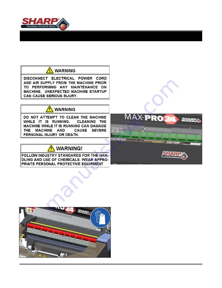
DRIVE & PLATEN ROLLERS


Regular cleaning of the Drive & Platen Rollers will 
keep the 

Sharp 

MAX

-

PRO 

running at optimum perfor-

mance.


1.


Remove power and air from bagger. 


2.


Release the Cradle Latch. 


3.


Wear PPE 

-

 Heat Resistant Gloves.


4.


Moisten a lint

-

free cloth with Isopropyl Alcohol and 

rub back and forth along Drive Roller (Shown in 
red). 


5.


Rotate roller and repeat until roller is clean.


6.


Repeat for Platen Roller (Shown in yellow).


7.


When rollers are clean, close the Cradle Latch.


8.


Return power and air to bagger.


PINCH ROLLER


After Cleaning the Drive Roller, clean the Pinch Roller 
in the Cradle Latch Assembly.


1.


Open the Cradle Latch.


2.


Pinch Roller (Shown in green) is behind Front Air 
Knife Cover but can be accessed from below cov-
er when Cradle is opened.


3.


Moisten a lint

-

free cloth with Isopropyl Alcohol and   

rub back and forth on the Pinch Roller. 


4.


Rotate roller and repeat until roller is clean.


5.


When roller is clean, close the Cradle Latch.


SECTION 3 - SET-UP & OPERATION 

Summary of Contents for MAX-PRO 1182

Page 1: ...Parts 1 262 246 8815 ext 1571 sharpparts pregis com Service 1 262 246 8815 ext 1572 sharpservice pregis com Original Printed English Copyright 2021 Rev 2 MAX PRO Operator Manual Models 1182 ...

Page 2: ...INTENTIONAL BLANK PAGE ...

Page 3: ...en Fingers 2 16 Integrated Exit Conveyor 2 17 Load Plate 2 18 Low And High Pressure Air 2 19 Pass Thru 2 20 Pressure Bar 2 21 Printer 2 22 Seal Bar 2 23 Seal Flatteners 2 24 Vacuum 2 25 Support Screen 2 26 SECTION 3 SET UP OPERATION Machine Placement Electrical Precautions 3 1 Grounding Instructions 3 1 Storage 3 1 Power Supply 3 2 Air Supply 3 3 Machine Adjustments Height Adjustment 3 3 Head Rota...

Page 4: ...modates 24 wide bags with an 12 pass through depth Save job settings and label designs in HMI for easy access Incorporating Zebra thermal printers permits direct printing onto the package for bar codes graphics and alphanumeric fonts Movable printing head sets to precise positions eliminating queuing and reducing material cost and scrap Decrease thermal ribbon usage as much ad 90 with reduced spac...

Page 5: ...a chine when tired ill or under the influence of alcohol drugs or medication The instructions and data in this manual are vital to the proper installation and operation of this equipment In order to avoid delays due to faulty installation and operation of the machine please see that these in structions are read by the persons who will install or operate or maintain the machine The WARNING instruct...

Page 6: ...ON if any of the ma chine s components have been removed or modified It is illegal to operate the equipment in an EU member state if the manual s is not written in that State s lan guage Contact your company if a translation is needed If the machine or parts of the machine have to be permanently put out of service laws and Directives in force at the time of the dismantling have to be strictly obse...

Page 7: ...ency Stop Button is located on the Control Panel which immediately stops the machine when pressed by de energizing power to the Master Control Relay PLC outputs motor motor drive and air valves OBSTRUCTION SENSING JAW The Sealing Assembly is equipped with Obstruction Sensing Sensors which can detect an obstruction in the Sealing Area If the Jaw Sensors detect and object preventing the Jaw from clo...

Page 8: ...h this label Side Crush This label is placed onto removable shields panels or guards near the Sealing Jaw of the Sharp MAX PRO to warn of potential crush danger Always disconnect electrical power from the machine prior to removing any guards and or panels Burn Hazard Label This label is placed onto removable shields panels or guards near the Heated Sealing Area of the Sharp MAX PRO to warn of pote...

Page 9: ...n to replace blown fuses ONLY with fuses with the same electrical rating Always dis connect electrical power before removing any guards and or panels and servicing the Sharp MAX PRO Fork Lift Use Label These labels are placed next to the lifting points for the Sharp MAX PRO bagger Only lift this bagger with a Fork Lift at these points LIFTING PROCEDURE The only approved lifting of this bagger is w...

Page 10: ...8815 ext 1572 E mail sharpservice pregis com SERIAL IDENIFCATION DECAL The serial number of the can be found on the Serial Identification Decal located on the rear of the bagger or inside of Electrical Box In the above example MAX PRO 24 Type of Sharp Bagger 21B The year and month bagger was built 1182 02 Model Number of bagger XXXX The number of bagger SPECIFICATIONS 1 5 BAG WIDTH BAG LENGTH FILM...

Page 11: ...MAX PRO Operator Manual Original Printed in English FRONT VIEW Bagger dimensions viewed from front Measurements are in inches MACHINE DIMENSIONS SECTION 1 INTRODUCTION 1 6 ...

Page 12: ...MAX PRO Operator Manual Original Printed in English TOP VIEW Bagger dimensions viewed from top Measurements are in inches MACHINE DIMENSIONS SECTION 1 INTRODUCTION 1 7 ...

Page 13: ...MAX PRO Operator Manual Original Printed in English SIDE VIEW Bagger dimensions viewed from side Measurements are in inches MACHINE DIMENSIONS SECTION 1 INTRODUCTION 1 8 ...

Page 14: ...ensity SPHD Polypropylene Sharp s Military Specification Film Gamma Patient Sharp s Metalized Barrier Film Electric Static Discharge ESD Modified Atmospheric Packaging MAP Sharp s Non Scratch Film E Z Stat Anti Static Vapor Corrosive Inhibitor VCI Contact Sharp Customer Service at 1 262 246 8815 to order Sharp EZ Bags and for information regarding film and bag specifications THERMAL TRANSFER RIBBO...

Page 15: ...ervice and Manufacturing icons are password protected Pressing any of these icons will prompt user to type in a password The Operator and Support icons are not password protected NOTE See Supervisor or Manager for correct password for each icon SECURITY SECTION 2 CONTROLS 2 1 ...

Page 16: ...nted in English SCREEN NAVIGATION HOME SCREEN This screen appears at machine start up and by pressing the home button on bottom left corner of screen Pressing any of the large buttons on this screen opens new screen SECTION 2 CONTROLS 2 2 ...

Page 17: ... saved in bagger Green light indicates which job is currently loaded LABEL PRINTER Status Reported status from Zebra Label Printer Pressing About button shows details of the printer Control Pause button pauses printer Only works if you are Service Factory User Darkness Allows user to change darkness of print Only works if you are a Service Factory User Reset Resets internal printer faults e g Prin...

Page 18: ...cle Time The average cycle time all cycles in seconds Reset Average Cycle Time Reset or clears the average cycle time SEAL BAR TEMPERATURE Current The current temperature of Seal Bar Required The temperature of Seal Bar per settings in loaded job MACHINE COUNTERS Informational display of counters and cycles of bagger OPERATOR BAGS Operator Resettable bag counter FILLER Toggles Filler ON or OFF BAG...

Page 19: ...Button from the Home Screen opens the Job Setup Screen This screen allows a Us er to configure Bag Dimensions and Feed Speed Bag Opening Package Eject Pressure Bar and Seal Bar Auxiliary Input output and Printer Access to this screen is password protected SCREEN NAVIGATION SECTION 2 CONTROLS 2 5 ...

Page 20: ... of the bag to the seal The typical setting is 5 to 1 5 inches less than the measured overall bag length Skirt Length The distance from the bottom of the bag to the start of the seal Width The width of the loaded bag Thickness The thickness of bag material BAG FEED SPEED Forward Adjusts the forward web speed in inches per second Reverse Adjusts the reverse web speed in inches per second LOW PRESSU...

Page 21: ... before feeding new bag out JAW PASS THRU Pass Thru Sets Pass thru will change move once job is loaded LOW PRESSURE AIR Press box in middle to set timeout for LPA at end of cycle to hold bag open Always OFF Always OFF Always ON Always ON HIGH PRESSURE AIR HP Air Dwell Sets the length of time in seconds the High Pressure Air blasts VACUUM Vacuum Dwell Sets the length of time in seconds that Vacuum ...

Page 22: ... EXIT CONVEYOR Runtime Timeout for External Exit Conveyor starts when package starts to fall INDEPENDENT BAG DEFLATOR Package Eject Delay Delays the start of Package Eject from normal firing time of the cycle Package Eject Dwell Timeout for Package Eject in discharge position INTEGRATED EXIT CONVEYOR Runtime Timeout for Integrated Exit Conveyor starts when package starts to fall LOAD PLATE Load Pl...

Page 23: ...losing the Pressure Bar SEAL BAR Dwell The amount of time the heated seal bar will remain in contact with the film High quality seals are accomplished through proper seal time settings These settings will vary with the film gauge and materi al Temperature Sets the desired temperature of seal bar Separate Before Seal Toggle switch that turns ON OFF a feature that prior to sealing the bag will rev e...

Page 24: ...rning appears when this is active OUTPUT 1 Not Configured No configuration Printer Data Ready Output active when Printer is ready for a new label Waiting For Printer Machine is cycling and film is backed up and ready to print but printer needs label Cycle Complete Cycle done Bag Made Bag is dropping Bag Made Label Required Bag is dropping AND printer needs a label Bags Low Bags low sensor is activ...

Page 25: ...ration Printer Data Ready Output active when Printer is ready for a new label Waiting For Printer Machine is cycling and film is backed up and ready to print but printer needs label Cycle Complete Cycle done Bag Made Bag is dropping Bag Made Label Required Bag is dropping AND printer needs a label Bags Low Bags low sensor is active SCREEN NAVIGATION SECTION 2 CONTROLS 2 11 ...

Page 26: ...c setting determines the distance the web will feed during the print cycle This should be set to smallest value that will produce the desired label This setting is approximately of inch longer than the length of the label Offset This numeric setting determines the starting position of the printed label This can be used to adjust the label position on the bag It is adjustable from 0 to 10 00 Clear ...

Page 27: ...l open the Appli cations Settings page Any changes made to this screen requires operator to press Load Job or Save Load button Application This allows a User to select HMI Language and to activate Demo Mode Demo Mode When demo mode is active the controller automatically sends a test label to the printer on every cycle SCREEN NAVIGATION SECTION 2 CONTROLS 2 13 ...

Page 28: ...d Green on PLC This screen allows a User to manually trigger Bag Position Bag Open Fingers Integrated Exit Conveyor Load Plate Low Pressure Air High Pressure Air Pass Thru Pressure Bar Printer Seal Bar Seal Flatteners and Vacuum Access to this screen is password pro tected HMI COMPUTER Minimize HMI Program This button will minimize the HMI program but leaves Operating System open SCREEN NAVIGATION...

Page 29: ...ght indicates the Photo eye detects bag Reverse Pressing Reverse button will reverse the web as long as button is pressed Forward Pressing Forward button will advance the web as long as button is pressed BAGS MADE Total Displays the total number of completed bags since last reset BAGS REJECTED Total The total number of bags that have been rejected since last reset Reset Counters Pressing Reset wil...

Page 30: ...wn Release Fingers will Rotate up to release the bag CYCLES Total The total number of cycle the Bag Open Fingers have completed since last reset OPEN RETRIES Total The total number of times the Bag Open Fingers have attempted to open fed bag Reset Counters Pressing Reset will clear the Cycles or Open Retries SCREEN NAVIGATION SECTION 2 CONTROLS 2 16 ...

Page 31: ...d to run exit conveyor until released This will changed the Dwell Apply To Settings Time that jog was pressed can be set to job dwell setting Job saves automatically but is not loaded PULSE DWELL Current Press to run conveyor at job setting Pulse Sec Press to run conveyor at job setting Setting Time for conveyor to run when Pulse Sec is pushed Changing this setting will save to job but not load th...

Page 32: ...ATE To Discharge Moves the Front Plate to the Discharge position To Load Moves the Front Plate to the Load Position REAR PLATE To Discharge Moves the Rear Plate to the Discharge position To Load Moves the Rear Plate to the Load Position CYCLES Total Displays the total number of complete Load Plate cycles since last reset Reset Counter Reset the Cycle Total Counter SCREEN NAVIGATION SECTION 2 CONTR...

Page 33: ...tting in loaded job Current The actual setting of Low Pressure Air blast Pulse Sec Runs Low Pressure Air for job setting dwell HIGH PRESSURE AIR Activate Turn on the High Pressure Air as long as button is pushed Current The amount of time the High Pressure Air will be ON according to setting in loaded job Setting The actual setting of High Pressure Air blast Pulse Sec Runs High Pressure Air for jo...

Page 34: ...es Face Plate Jog OUT Moves Jaw outward as long as button is pushed or until it reaches end of travel MANUAL POSITION Current The actual width of Jaw Move To In Moves Jaw to width set in job settings Setting Active job setting for Pass thru POSITION CHANGES Total Displays the total number of changes to Pass thru since last reset Reset Counters SCREEN NAVIGATION SECTION 2 CONTROLS 2 20 ...

Page 35: ...or close the Pressure Bar Pressure Bar will remained closed until Move OUT is pushed Move OUT Pressing this button will extend or open the Pressure Bar CYCLES Total Total number of Cycles the Pressure Jaw has completed since last reset Reset Counter Resets the Total Cycles Counter SCREEN NAVIGATION SECTION 2 CONTROLS 2 21 ...

Page 36: ...Labels In Queue The number of labels loaded into printer Clear Queue Clears the Queue of loaded labels Send Test Sends one Test Label to printer for a test print Send File Opens a Select Label File Dialog Box User can navigate to stored labels on computer to load into Job CONFIGURATION Expert use only Darkness Allows user to change darkness setting Settings Exposes all available printer settings e...

Page 37: ...e IN button is pressed CYCLE Current Displays the length of time Seal Bar is active Pulse Sec Cycles the Seal Bar There must be a time set in Job Settings Current or Seal Bar will not move Setting Displays the Job Setting for temperature SEAL BAR CYCLES Total Number of completed Seal Bar Cycles since last reset Reset Counter Resets the Seal Bar Cycles Counter SCREEN NAVIGATION SECTION 2 CONTROLS 2...

Page 38: ...ton is pressed or until fingers reach center Jog OUT Moves fingers OUT as long as button is pressed or until fingers are completely out MANUAL POSITION Current This setting determines the IN setting for the fingers Move To In This button moves the fingers to the Current Setting If Current Setting is zero fingers will move to center of sealing area CYCLES Totals The number of completed Seal Flatten...

Page 39: ...n Vacuum Vacuum will stay on until button is pressed again DWELL Current The actual setting of the Vacuum ON Pulse Sec Pressing the button will turn Vacuum ON for length of Dwell Setting Setting The actual length of Vacuum on when button is pushed SCREEN NAVIGATION SECTION 2 CONTROLS 2 25 ...

Page 40: ...ides the contact information for Sharp Service and Sharp Parts Also provides Sharp Packaging Systems mailing address SOFTWARE VERSIONS Displays current Software Upgrade From File Allows for mapping to saved HMI program file used to upgrade program 2 25 SCREEN NAVIGATION SECTION 2 CONTROLS ...

Page 41: ...ng an equipment grounding conductor for a 3 prong grounding plug The plug must be connected into an outlet that is properly installed and grounded in the accordance with all local codes and ordinances Do not modify the plug provided with the machine If your electrical supply does not meet the above specifications or if you are unsure your building has an effective ground have a qualified electrici...

Page 42: ...position 2 Plug Male End of Power Cord into properly grounded wall outlet or electrical drop 3 Insert Female End of Power Cord into the Power Entry Module on back of Electrical Box The box is in the Frame Assembly 4 Turn the switch on the Power Entry Module to ON position 5 Plug the Male End of second Power Cord into a properly grounded wall outlet or electrical drop 6 Insert the Female end into P...

Page 43: ... Do not use a lubricator or lubricated air on the machine Damage to valves and cylinders will occur 1 Connect Air Hose to Regulator 2 Unlock Cap on Regulator 3 Adjust to 80 PSI 4 Lock Cap on Regulator HEIGHT ADJUSTMENT Machine height can be adjusted to allow manual load ing at a convenient height 1 Navigate to Service Screen 2 Locate the Bagger Head window 3 Adjust height to desired position Head ...

Page 44: ...hten the Rotating Clamp Screws LOAD SHELF The Load Shelf can be moved up or down to accom modate different sized bags 1 Loosen the Locking Handles on back of Load Plate 2 Move Load Shelf to desired location 3 Tighten the Locking Handles LOAD PLATE The Load Plate angle can be changed to provide bet ter support of bag 1 Remove the Ring Pin from back of Load Plate move plate to desired location and r...

Page 45: ...when standing behind box 1 Raise the Cradle Printhead Cradle and Unwind Cradle by rotating the Latches and open the Cra dles 2 While standing at the right side of the machine feed film over Drag Tube of Box Tray 3 Then under over Unwind Drag Tubes then under Idler Roller finally over the Unwind Drive Roller Close Unwind Cradle Latch Position Weight Straps over Box Tray Drag Tube 3 5 Use extreme ca...

Page 46: ...ed in English 4 Pull the film Under the Printer Carriage until edge drapes over the Platen and Drive Rollers and down past the Front Finger Plate 5 Lower and lock the Drive Roller Cradle Latch LOADING BAG FILM 3 6 SECTION 3 SET UP OPERATION ...

Page 47: ...ard tube into carriage let hang loose 4 Place a new roll of ribbon onto the Ribbon Unwind hub 5 Thread the ribbon under Ribbon Roller Sleeve under Return Ribbon Shaft around Printhead then up and over Ribbon Return Shaft to Ribbon Rewind Hub 6 Place empty cardboard roll onto Ribbon Rewind Hub 7 Turn knob on Take Up Spool counter clockwise to ensure ribbon is tight 8 Close the Printhead Cradle Cove...

Page 48: ...bagger NOTE The machine will display several faults and warnings when HMI program and Power Button have been pressed 7 Press the Enable Bagger Button This will estab lish communication and clear faults of Home Pres sure Bar Seal Flattener and Bag Feed 8 The Seal Bar Not At Temperature warning will remain until Seal Bar reaches loaded job tempera ture setting 9 Press the Operator button to open Ope...

Page 49: ...ine surfaces Particles of steel wool may break off and cause rusting or contaminate lubricated surfaces DO NOT allow wrenches fittings or other metallic objects to lie on machine surfaces during opera tion DO NOT use chlorine ammonia alkalis acids or cleaning solutions that will damage metallic ma chine surfaces cause corrosion or contaminate containers SEVERE DUTY APPLICATIONS Some applications m...

Page 50: ...nspect the Unwind Pinch Roller Clean as needed See Unwind Pinch Roller Cleaning Procedure page 2 10 Verify the Pinch Roller spins freely when latch is opened Inspect the Teflon Tape that covers the Pres sure Bar Anvil Rubber and replace if worn or damaged MONTHLY CLEANING MAINTENANCE All of Weekly maintenance Inspect the Air Filter for debris and replace as necessary Inspect all external wiring fo...

Page 51: ...rty Do not use any solvents or cleaning solutions on the sensing por tions of eye PRINTHEAD 1 Turn the Printer Control Box OFF 2 Open the Printer Carriage by releasing the Draw Latch on side of Printer Carriage 3 Clean the Printhead thoroughly using a soft lint free cloth and 99 7 isopropyl alcohol Bag Edge Present Sensor SECTION 3 SET UP OPERATION ...

Page 52: ...d repeat until roller is clean 6 Repeat for Platen Roller Shown in yellow 7 When rollers are clean close the Cradle Latch 8 Return power and air to bagger PINCH ROLLER After Cleaning the Drive Roller clean the Pinch Roller in the Cradle Latch Assembly 1 Open the Cradle Latch 2 Pinch Roller Shown in green is behind Front Air Knife Cover but can be accessed from below cov er when Cradle is opened 3 ...

Page 53: ...p the machine according and apply air to regulator 2 Release the E Stop Button and press the Green Power Button 3 Allow Seal Bar Shown in orange to reach set temperature 4 Access the Service Screen from the Main Screen The Service Screen is passcode protect ed See Supervisor to gain access 5 Press the Extend Seal Bar Button to change the state of the Seal Bar 6 Wear PPE Heat Resistant Gloves 7 NEV...

Page 54: ... Alcohol and rub back and forth along Unwind Drive Roller Shown in purple 4 Rotate roller and repeat until roller is clean 5 PINCH ROLLER After Cleaning the Unwind Drive Roller clean the Un wind Pinch Roller in the Latch Assembly 1 Open the Cradle Latch 2 Moisten a lint free cloth with Isopropyl Alcohol and rub back and forth on the Pinch Roller Shown in pink 3 Rotate roller and repeat until rolle...

Page 55: ... the Bag ger Enabled button E Stop tripped or Power not Re set E Stop Button was pressed or E Stop is released but the Green Pow er Button has not been pressed Release the E Stop press the Green Power Button and the Bag ger Enabled button Seal Bar Thermal Runaway Not Heating Seal Bar not heating up at all or not as quickly as expected A qualified service person should test the Thermocouple and its...

Page 56: ...ontroller and I O master have been interrupt ed Verify cables are connected and tightened properly Communication Fail I O Master to I O Node Communications between I O Mas ter and expected I O node have been interrupted Verify cables are connected and tightened properly Master I O Communication Fail ure Controller Disconnected The controller is disconnected Connect the controller Palm Button Confi...

Page 57: ...filled and sealed in Filler Mode No action is required Bag Level Low Bag are getting low in box Prepare to replace bags soon Demo Mode Is Active Bagger s demo mode is active Disable demo mode in Set tings Demo to turn off this warning Factory Test Mode Is Active Bagger is running in Test Mode Turn Factory Test OFF in Factory Setup Factory Test Machine Not Tested Bagger life cycle count is not over...

Page 58: ...ied Product Install a genuine Zebra print head Head Element Out A printhead element is no longer working If the location of the failed ele ment affects printing replace the printhead Replace Printhead The printhead is nearing the end of its life and should be replaced Replace the printhead Head Maintenance Needed The printhead needs to be cleaned Clean the printhead See Clean ing the Printhead on ...

Page 59: ... print line is not at an optimal position for your media Adjust the print line for thick media Print Consistently Too Light or Too Dark Issue Possible Cause Possible Solution s Printing is too light or too dark over the entire label The Printer is set at an incorrect darkness level For optimal print quality set the darkness to the lowest possible setting for your application Incorrect printhead pr...

Page 60: ...le Cause Possible Solution s Fine angular gray lines on blank labels Wrinkled ribbon Verify the ribbon is loaded properly smooth out ribbon Missing Print Issue Possible Cause Possible Solution s Long tracks of missing print on several labels Print element damaged Call for service Wrinkled ribbon Verify the ribbon is loaded properly smooth out ribbon ...

Page 61: ...ine which is returned transportation prepaid to Sharp s authorized service center within the warranty period The warranty starts on the date the machine is delivered to the original Buyer and expires one 1 year for parts and ninety 90 days for labor after that date Buyer at Sharp s request shall provide documents establishing the delivery date Exclusions This war ranty shall not apply to a any mac...

Page 62: ...MAX PRO Operator Manual Original Printed in English APPENDIX A 5 2 ...

Page 63: ...MAX PRO Operator Manual Original Printed in English APPENDIX A 5 3 ...

Reviews: