11
LC-22LE250
LC-24LE250
Operation Manual (Continued)
English
- 11 -
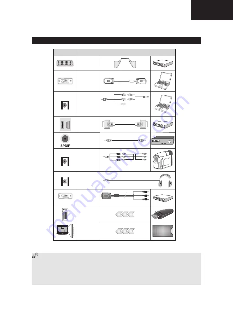
NOTE: When connecting a device via the YPbPr or Side AV input, you must use a connection cables
to enable connection. See the illustrations above. | To enable PC audio, you will need to use the SIDE AV
CONNECTION cable’s WHITE & RED inputs. | If an external device is connected via the SCART socket, the TV
will automatically switch to AV mode.| When receiving DTV channels (Mpeg4 H.264) or while in Media Browser
mode, output will not be available via the scart socket. | When using the wall mounting kit (optional), we recommend
that you plug all your cables into the back of the TV before mounting on the wall. | Insert or remove the CI module
only when the TV is SWITCHED OFF. You should refer to the module instruction manual for details of the settings.
Connector
Type
Cables
Device
Scart
Connection
(back)
VGA
Connection
(back)
SIDE AV
S
IDE
A
V
PC/YPbPr
Audio
Connection
(side)
Side Audio/Video
Connection Cable
(Supplied)
PC Audio Cable
(Not supplied)
HDMI
Connection
(back)
SPDIF
Connection
(back)
SIDE AV
S
IDE
A
V
Side AV
(Audio/Video)
Connection
(side)
AV Connection Cable
(supplied)
HEADPHONE
Headphone
Connection
(side)
PC to YPbPr
YPbPr Video
Connection
(back)
PC to YPbPr Connection Cable (Not supplied)
USB
Connection
(side)
CI
Connection
(side)
CAM
module
Viewing the Connections
A01_[GB]_MB95S_4847UK_DVBT_C_24205LED_ROCKER_SILVER16_10081844-10083115_50232547_basic IB.indd 11
28.01.2013 15:50:14
Summary of Contents for LC-24LE250V-BK
Page 12: ...12 LC 24LE250 LC 22LE250 DIMENSIONS English 20 Dimensional Drawings LC 22LE250 ...
Page 13: ...13 LC 22LE250 LC 24LE250 English 21 Dimensional Drawings LC 24LE250 ...
Page 16: ...16 LC 24LE250 LC 22LE250 3 Remove Speaker Wire 4 Remove AC Cord ...
Page 18: ...18 LC 24LE250 LC 22LE250 1 1 General Block Diagram 15 General Block Diagram ...
Page 19: ...19 LC 22LE250 LC 24LE250 1 2 Placement of Blocks ...
Page 22: ...22 LC 24LE250 LC 22LE250 ...
Page 25: ...25 LC 22LE250 LC 24LE250 10 Table 2 Pin functions ...
Page 32: ...32 LC 24LE250 LC 22LE250 17 Table 5 Recommended operating conditions Figure 7 Pin description ...
Page 34: ...34 LC 24LE250 LC 22LE250 ...
Page 35: ...35 LC 22LE250 LC 24LE250 ...
Page 38: ...38 LC 24LE250 LC 22LE250 ...
Page 39: ...39 LC 22LE250 LC 24LE250 ...
Page 40: ...40 LC 24LE250 LC 22LE250 ...
Page 41: ...41 LC 22LE250 LC 24LE250 ...
Page 59: ...59 LC 22LE250 LC 24LE250 ...
Page 63: ...63 LC 22LE250 LC 24LE250 MENU Return Exit Ret Back SRS Video Settings ...
Page 105: ...105 LC 22LE250 LC 24LE250 ...


