background image

US

18

a

b

c

d

w

x

y

z

1H

1V

VIDEO SIGNAL

HORIZONTAL
SYNC SIGNAL

VERTICAL
SYNC SIGNAL

VIDEO SIGNAL

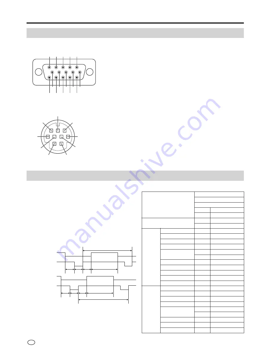
Connecting to computer

Connection Pin Assignments

1

2

3

4

5

11

12

13

14

15

6

7

8

9

10

8

7

3

6

9

5

4

1

2

RGB input terminal: 15-pin mini D-sub female connector

CONTROL terminal: 9-pin mini Din female connector

Pin No.

1
2
3
4
5
6
7
8
9

Signal

-

RD

SD

-

SG

-

RS

-
-

Name

Receive Data
Send Data

Signal Ground

Request to send

I/O

Input

Output

Output

Reference

Not connected
Connected to internal circuit
Not connected
Connected to internal circuit
Not connected
Connected to internal circuit
Not connected
Not connected

Pin No.

1
2
3
4
5
6
7
8

Signal

Analog input(red)
Analog input(green)
Analog input(blue)
Not connected
Composite sync
GND (Analog red)
GND (Analog green)
GND (Analog blue)

Pin No.

9

10
11
12
13
14
15

Signal

Not connected
GND
GND
Not connected
Horizontal sync signal
Vertical sync signal
Not connected

dot

line

LEVEL

TYPE
dot

dot

dot

dot

dot

µ

s

ns

kHz

MHz

+ / –

H

H

H

H
H

ms

Hz

+ / –

MODE

VIDEO

H-SYNC

V-SYNC

RGB Input Signals (Recommended Timing)

Input signal

Video signal:

Analog input 0 to 0.7Vp-p 75

 terminal (positive

polarity)

Horizontal synchronizing signal:

TTL level (negative polarity)

Vertical synchronizing signal:

TTL level (negative polarity)

Video signal time chart

IBM, DOS/V type

IBM

VGA

GRAPHIC

640

480

0.7Vp-p, 75

 load

RGB

-

-

50

640

800

31.7776

39.7219

31.4688

25.175

TTL

-

-

32

480

525

16.6832

59.9405

TTL

FRONT PORCH a

SYNC

b

BACK PORCH

c

VIDEO PERIOD d

1H

1dot

1/H

1/dot

LEVEL

SYNC POLARITY

FRONT PORCH w

SYNC

x

BACK PORCH

y

VIDEO PERIOD z

1V

1/V

LEVEL

SYNC POLARITY

Summary of Contents for LC-20VM2

Page 1: ... 20VM2 LCD AV MONITOR MONITEUR AV À CRISTAUX LIQUIDES MONITOR AV LCD MONITOR AV DE TELA DE CRISTAL LÍQUIDO PRINTED IN JAPAN IMPRIMÉ AU JAPON IMPRESO EN JAPÓN IMPRESSO NO JAPÃO TINS 6901CEZZ TXXXX A SHARP CORPORATION OSAKA JAPAN LC 20VM2 ENGLISH FRANÇAIS ESPAÑOL PORTUGUÊS ...

Page 2: ...protection against harmful interference in a residential installation This equipment generates uses and can radiate radio frequency energy and if not installed and used in accordance with the instructions may cause harmful interference to radio communications However there is no guarantee that interference will not occur in a particular installation If this equipment does cause harmful interferenc...

Page 3: ...ENGLISH OPERATION MANUAL ENGLISH ...

Page 4: ...ean the product Do not use liquid cleaners or aerosol cleaners 6 Attachments Do not use attachments not recommended by the manufacturer Use of inadequate attachments can result in accidents 7 Water and moisture Do not use the product near water such as bathtub washbasin kitchen sink and laundry tub swimming pool and in a wet basement 8 Stand Do not place the product on an unstable cart stand tripo...

Page 5: ...owing conditions occurs unplug the power cord from the AC outlet and request a qualified service person to perform repairs a When the power cord or plug is damaged b When a liquid was spilled on the product or when objects have fallen into the product c When the product has been exposed to rain or water d When the product does not operate properly as described in the operating instructions Do not ...

Page 6: ...tery 2 UBATU0026GEZZ MENU SELECT MUTE AV INPUT ON OFF VOL VOL SELECT Make sure the following accessories are provided with the product Supplied Accessories Din D sub RS232C cable 1 QCNW 5288CEZZ 78 3 4 2m 59 1 16 1 5m 78 3 4 2m OPERATION MANUAL MODE D EMPLOI MANUAL DE MANEJO MANUAL DE OPERAÇÃO LC 20VM2 LCD AV MONITOR MONITEUR AV À CRISTAUX LIQUIDES MONITOR AV LCD MONITOR AV DE TELA DE CRISTAL LÍQU...

Page 7: ...ith their terminals corresponding to the and indications Different types of batteries have different characteristics Do not mix batteries of different types Do not mix old and new batteries Mixing old and new batteries can shorten the life of new batteries and or cause old batteries to leak chemicals Remove batteries as soon as they are non operable Chemicals that leak from batteries can cause a r...

Page 8: ...erminal then insert cables into the main unit Clamping the connection cords Preparation Removal Remove the back cover when inserting the cords into the terminals To remove the back cover gently pull the part marked forward Mounting Insert the four hooks 1 into the cabinet Making the back cover bulge forward insert the four hooks 2 into the cabinet Press on the marked parts 3 until the two hooks on...

Page 9: ...indow 2 HEAD PHONE jack 3 MENU button 4 VOL buttons 5 SELECT buttons 6 AV INPUT button 7 POWER switch 8 POWER indicator MENU button VOL buttons SELECT buttons and AV INPUT button have the same function as those on the remote control This manual describes button functions by referring to the buttons on the remote control Front Control section ...

Page 10: ...EO S VIDEO R L VIDEO AV INPUT 1 AV INPUT 2 AV OUT COMPONENT INPUT Y PB CB PR CR R L POWER INPUT DC13V AUDIO AUDIO VIDEO AUDIO NTSC PAL SECAM NTSC PAL AUDIO INPUT RGB INPUT VGA60Hz 1 2 3 4 0 9 7 5 8 6 q 7 AUDIO input terminal AV INPUT 2 AV OUT 8 VIDEO input terminal AV INPUT 2 AV OUT 9 VIDEO input terminal COMPONENT 0 AUDIO input terminal COMPONENT q DC input terminal 7 and 8 can also be used as vi...

Page 11: ...ion MENU HEAD PHONE AV INPUT SELECT VOL POWER POWER MENU SELECT MUTE AV INPUT ON OFF VOL VOL SELECT MENU SELECT MUTE AV INPUT ON OFF VOL VOL SELECT MENU SELECT MUTE AV INPUT ON OFF VOL VOL SELECT MENU SELECT MUTE AV INPUT ON OFF VOL VOL SELECT The front control section of the main unit is also provided with the AV INPUT SELECT VOL and MENU buttons This manual describes button functions by referrin...

Page 12: ...er each time AV INPUT is pressed Note 1 AV input mode indication remains for three seconds 2 To change the AV input mode press AV INPUT while the AV input mode is displayed within 3 seconds AV1 Video equipment connected to the AV1 input terminals S video input terminal is additionally provided for the AV1 input If both S video and normal video terminal is connected with cables the S video input te...

Page 13: ...und Press MUTE to temporarily turn off the sound Screen display flashes Press MUTE or VOL to turn the sound back to the previous level Power ON OFF standby To turn off the monitor press Power ON OFF The Power indicator will turn red To turn the monitor back on press Power ON OFF again The Power indicator will turn green Basic Operation MENU SELECT MUTE AV INPUT ON OFF VOL VOL SELECT VOLUME 5 VOLUM...

Page 14: ...ts are received Switching the System Set the system to AUTO for normal reception The AUTO mode automatically detects the receiving signal system and changes the reception system of the set When the picture or sound is not stable switching to an appropriate system may improve the picture or sound quality Adjustment MENU SELECT MUTE AV INPUT ON OFF VOL VOL SELECT MENU PICTURE SOUND PRESET MENU PICTU...

Page 15: ...ONTRAST 3 Decrease contrast Increase contrast TINT Toward purple Toward green COLOR 3 Lower color intensity Higher color intensity BLACK LEVEL Less bright More bright SHARPNESS Soft picture Hard picture RED Less red level More red level BLUE Less blue level More blue level COLOR SYSTEM AUTO Press VOL to select color system AUTO N358 N443 PAL PAL M SECAM Note If no button is pressed for more than a...

Page 16: ... L C TREBLE Lower treble level Higher treble level BASS Lower bass level Higher bass level BALANCE L3 R3 Press VOL to select speaker and Line out settings SPEAKER ON SPEAKER OFF LINE OUT STABLE LINE OUT VARIABLE Shift center of sound toward left Shift center of sound toward right MENU SELECT MUTE AV INPUT ON OFF VOL VOL SELECT MENU PICTURE SOUND PRESET MENU PICTURE SOUND PRESET SOUND SPEAKER ON LI...

Page 17: ...NPUT 2 MONO Only the audio signals entering from the AUDIO L terminal are output from the left and right speakers MODE 2 MODE 2 is a calculated scan conversion mode and is suited for normal pictures The scan conversion modes work in PAL and SECAM ABC A B C MENU PICTURE SOUND PRESET MENU PICTURE SOUND PRESET PRESET BRIGHTNESS BRIGHT UPSIDE NORMAL RIGHT LEFT NORMAL AV2 IN OUT IN AV1 LINE NORMAL SCRE...

Page 18: ...ress VOL to make adjust ment Selected item Press VOL Press VOL Adjustment MENU SELECT MUTE AV INPUT ON OFF VOL VOL SELECT CLOCK PHASE 1 H POS V POS Set to the position at which there is the least noise Set to the position at which there is the least noise Move the on screen image to the left Move the on screen image upward Move the on screen image to the right Move the on screen image downward MEN...

Page 19: ...rizontal scanning frequency Clock frequency Note Horizontal dots Vertical lines Vertical frequency IBM PC DOS V PC V PC AT 640 480 31 4688 kHz 25 175 MHz VGA and compatible computers 59 9405 Hz Handling of the RGB Connection Cable Align the pins of this unit and those of the RGB connection cable used to connect the computer and insert then securely fasten with the screws located at both ends Push ...

Page 20: ...put green Analog input blue Not connected Composite sync GND Analog red GND Analog green GND Analog blue Pin No 9 10 11 12 13 14 15 Signal Not connected GND GND Not connected Horizontal sync signal Vertical sync signal Not connected dot line LEVEL TYPE dot dot dot dot dot µs ns kHz MHz H H H H H ms Hz MODE VIDEO H SYNC V SYNC RGB Input Signals Recommended Timing Input signal Video signal Analog in...

Page 21: ... volume can be adjusted and various other adjustments and settings can be made enabling automatic programed playing Attach an RS232C cable cross type commercially available to the supplied Din D sub RS232C for the connections Note This operation system should be used by a person who is accustomed to using computers Connections Connect this unit with the RS232C terminal of the computer Send the con...

Page 22: ...tus cannot be read to the computer Therefore confirm the status by transmitting the display commands for each adjustment menu and checking the status with the On screen Display If the LCD Monitor receives a command other than a menu display command it will execute the command without displaying the On screen Display Commands Example The AV input mode set to PAL after switching the display mode to ...

Page 23: ...SET INVERT OFF INVERT ON REVERSE OFF REVERSE ON INPUT DISPLAY OFF INPUT DISPLAY ON DISPLAY Note If a dash _ appears in the parameter column enter a space If an asterisk appears enter a value in the range indicated in brackets under CONTROL CONTENTS COMMAND PARAMETER C1 C2 C3 C4 P1 P2 P3 P4 V A P I _ V A B R _ V A C O _ V A T I _ V A S H _ V A R D _ V A B E _ V A R E _ _ _ 0 V A R E _ _ _ 1 V B P I...

Page 24: ...or wiring Note Refer to the manual how to connect these tuner to the room antenna terminal Connecting to Video Equipment Via TV Via Satellite TV Pay TV AUDIO To VIDEO AUDIO input terminal To VIDEO AUDIO output terminal AUDIO To VIDEO AUDIO input terminal To VIDEO AUDIO output terminal VIDEO L R VCR TV TUNER VIDEO L R SATELLITE TUNER SET TOP BOX FOR PAY TV ...

Page 25: ...cting to Video Equipment To VIDEO AUDIO input terminal To VIDEO AUDIO output terminal To S VIDEO input terminal To S VIDEO output terminal SET TOP BOX WEB TV GAME UNIT R L VIDEO S VIDEO AUDIO Via Web TV Game Unit ...

Page 26: ...follows Connecting to Video Equipment TUNER BAND DVD AUX 1 AUX 3 AUX 2 SURROUND ON OFF To AUDIO input terminal of COMPONENT To AUDIO output terminal of COMPONENT To VIDEO input terminal of COMPONENT To VIDEO output terminal of COMPONENT COMPONENT INPUT Y PB CB PR CR R L AUDIO VIDEO DVD PLAYER Digital Video Disc ...

Page 27: ...inal To S VIDEO output terminal To VIDEO AUDIO input terminal To VIDEO AUDIO input terminal To VIDEO AUDIO output terminal To VIDEO AUDIO output terminal AUDIO AV INPUT 1 AV INPUT 2 VIDEO S VIDEO L R AUDIO VIDEO L R VIDEO CAMERA ETC GAME UNIT Video Game unit ...

Page 28: ...re headphone is not connected Check to see if Brightness adjustment is not set to DARK Screen brightness can be set to three levels DARK NORMAL and BRIGHT Make sure Contrast and Brightness adjustments are not set too low Lamp may have reached the end of life Contact a Sharp service shop for lamp replacement Check Color adjustment Make sure proper color system is set In the case of component mode c...

Page 29: ...LS AV input 2 Audio R L Video RCA composite Component input Audio R L Video Y PB CB PR CR RGB input Audio φ3 5 R L VGA 60Hz computer input Control RS232C Headphone jack Mini jack for stereo POWER SUPPLY DC operation DC 13V AC operation AC100 240V with AC adapter Power consumption 50 7 W APPEARANCE Exterior color Silver Outside dimensions 18 1 8 W 17 9 64 H 7 3 32 D with stand 460 W 435 H 180 D mm ...

Page 30: ...US 28 Dimensional Drawings 7 3 32 179 9 mm 15 63 64 406 mm 17 9 64 435 mm 18 1 8 460 mm 15 53 64 402 mm 1 61 64 49 5 mm 13 32 10 5 mm 1 23 32 44 mm 7 8 32 180 mm ...

Page 31: ...29 US Memo ...

Reviews: