LC-15A2U
10
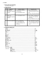
3. Cancel of special mode
Turn off the main unit power.
4. Adjustments
Adjustment
Adjusting conditions
Adjusting method
1
B+ Adjustment
1. Connect the DC voltmeter to
1. Adjust the "B+ Adj" value to
(If E
2
PROM is replaced)
pin 49 of SC401.
5.0V
±
0.02V with [VOL+] or [VOL-]
(IC2004)
2. Go to the adjustment mode.
Key.
* The color of "B+ Adj" must be yellow.
2
Model setup
1. Go to the adjustment mode.
1. Select "MODEL" with [MENU] key
(If E
2
PROM is replaced)
and adjust to "A2U" with [VOL+]
(IC2004)
or [VOL-] key.
* The color of "MODEL" must be yellow.
3
Counter-bias adjustment
1. Receive a B/W channel.
1. Adjust "COM BIAS" to the darkest
2. Go to the adjustment mode.
screen with [VOL+] and [VOL-] key.
3. Select the "COM BIAS" with
* The color of "COM BIAS" must be
[MENU] key.
yellow.
5. Shipping setting list
Channel ............................................................................................................................................... 2ch
Air/Cable ............................................................................................................................................. Air
Skip Data_CATV ................................................................................................................................. All Skip
Skip Data_AIR .................................................................................................................................... All Skip
Volume ................................................................................................................................................ 20
Picture ................................................................................................................................................. 30
Tint ...................................................................................................................................................... 0
Color ................................................................................................................................................... 0
Black Level ......................................................................................................................................... 0
SHARP ................................................................................................................................................ 0
RED-BLUE .......................................................................................................................................... 0
GREEN ............................................................................................................................................... 0
TV Color System ................................................................................................................................. N358
AV Color System ................................................................................................................................ Auto
Language ............................................................................................................................................ English
Blue Screen ........................................................................................................................................ Off
EZ Setup Auto Start ............................................................................................................................ On
Sleep Timer ........................................................................................................................................ None
MTS .................................................................................................................................................... Stereo
Brightness ........................................................................................................................................... Bright
Auto Power Off ................................................................................................................................... Off
Upside ................................................................................................................................................. Normal
Right/Left ............................................................................................................................................ Normal
AV1 ..................................................................................................................................................... Normal
AV2 IN/OUT ........................................................................................................................................ In
Closed Caption (Mode) ...................................................................................................................... OFF
(Data) ....................................................................................................................... CH1
V Chip block
(MPAA) ..................................................................................................................... None
(TV Guideline) .......................................................................................................... None
(Block Content) ........................................................................................................ All Unblock
(Status) ..................................................................................................................... Off
(Input Secret No.) ..................................................................................................... Clear
Summary of Contents for LC 15A2U
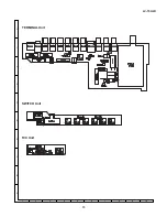
Page 15: ...15 LC 15A2U A B C D E F G H I J 1 2 3 4 5 6 7 8 9 10 TERMINAL Unit SWITCH Unit R C Unit ...
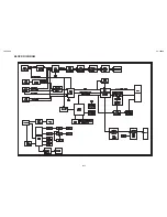
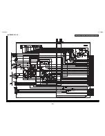
Page 16: ...LC 15A2U LC 15A2U BLOCK DIAGRAM 16 17 ...
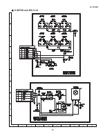
Page 18: ...19 LC 15A2U Ë SWITCH and R C Unit A B C D E F G H I J 1 2 3 4 5 6 7 8 9 10 ...
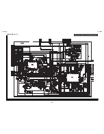
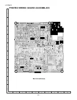
Page 23: ...27 LC 15A2U Main Unit Side B A B C D E F G H I J 1 2 3 4 5 6 7 8 9 10 ...
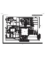
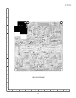
Page 24: ...28 LC 15A2U A B C D E F G H I J 1 2 3 4 5 6 7 8 9 10 Terminal Unit Side A ...
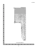
Page 25: ...29 LC 15A2U A B C D E F G H I J 1 2 3 4 5 6 7 8 9 10 Terminal Unit Side B ...
Page 37: ...41 Ref No Part No Description Code Ref No Part No Description Code LC 15A2U M E M O ...
Page 38: ...42 LC 15A2U Ref No Part No Description Code Ref No Part No Description Code M E M O ...
Page 39: ...43 Ref No Part No Description Code Ref No Part No Description Code LC 15A2U ...


