


18
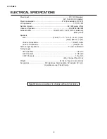
LC-15A2U
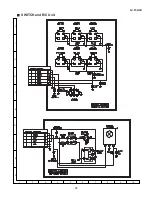
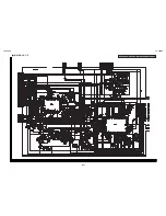
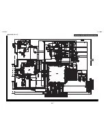
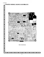
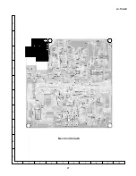
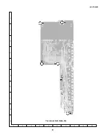
DESCRIPTION OF SCHEMATIC DIAGRAM
1. When the exclusive-use AC adapter is used, the color
bar signal of color bar generator for service is input
to get the normal screen. When the audio is
minimized, the voltage value is measured with the
20 k
Ω
/V tester.
2. When the exclusive-use AC adapter is used, the color
density, lightness and color hue are set to the center
position, and the signal of color bar generator for
service is observed to get waveform.
The wave form test point is indicated with the mark
(
) in the wiring diagram.
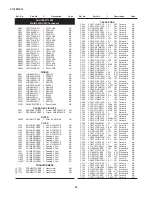
3. Indication of resistors and capacitors
[Resistors]
Unit
: Nonindication …
Ω
, K…k
Ω
,
M … M
Ω
Error : Nonindication …
±
10%
J …
±
5%
F …
±
1%
D …
±
0.5%
[Capacitor]
Unit
: Nonindication or
µ
…
µ
F,
P or p … pF
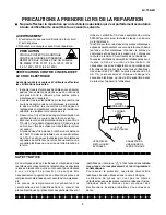
IMPORTANT SAFETY NOTICE:
PA RT S M A R K E D W I T H "
å
" (
)
A R E
INPORTANT FOR MAINTAINING THE SAFETY OF
THE SET.
BE SURE TO REPLACE THESE PARTS WITH
SPECIFIED ONES FORMAINTAINING THE SAFETY
AND PERFORMANCE OF THE SET.
CAUTION:
This circuit diagram is original one, therefore there
may be a slight difference from yours.
Resistors
Nonindication
Carbon-film resistor
C
Solid resistor
S
Metal-oxide-film resistor
N
Metal-film resistor
W
Cement resistor
T
Special resistor
Capacitors
Nonndication
Ceramic capacitor
ML
Mylar capacitor
PF
Polypropylene
film capacitor
TA
Tantalum capacitor
Styrol capacitor
AVIS DE SECURITE IMPORTANT:
LES PIECES MARQUEES "
å
"
( )
SONT
IMPORTANTES POUR MAINTENIR LA SECURITE
DE L'APPAREIL.
NE REMPLACER CES PIECES QUE PAR DES
PIECES DONT LE NUMERO EST SPECIFIE POUR
MAINTENIR LA SECURITE ET PROTEGER LE
BON FONCTIONNEMENT DE L'APPAREIL.
[Item]
Summary of Contents for LC 15A2U
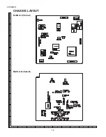
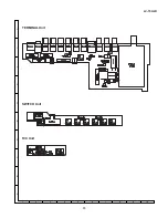
Page 15: ...15 LC 15A2U A B C D E F G H I J 1 2 3 4 5 6 7 8 9 10 TERMINAL Unit SWITCH Unit R C Unit ...
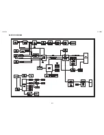
Page 16: ...LC 15A2U LC 15A2U BLOCK DIAGRAM 16 17 ...
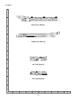
Page 18: ...19 LC 15A2U Ë SWITCH and R C Unit A B C D E F G H I J 1 2 3 4 5 6 7 8 9 10 ...
Page 23: ...27 LC 15A2U Main Unit Side B A B C D E F G H I J 1 2 3 4 5 6 7 8 9 10 ...
Page 24: ...28 LC 15A2U A B C D E F G H I J 1 2 3 4 5 6 7 8 9 10 Terminal Unit Side A ...
Page 25: ...29 LC 15A2U A B C D E F G H I J 1 2 3 4 5 6 7 8 9 10 Terminal Unit Side B ...
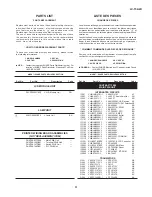
Page 37: ...41 Ref No Part No Description Code Ref No Part No Description Code LC 15A2U M E M O ...
Page 38: ...42 LC 15A2U Ref No Part No Description Code Ref No Part No Description Code M E M O ...
Page 39: ...43 Ref No Part No Description Code Ref No Part No Description Code LC 15A2U ...