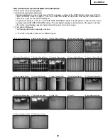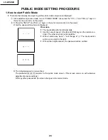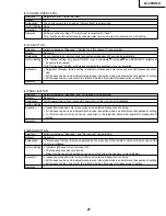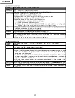
LC-20SH4U
37
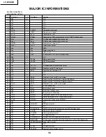
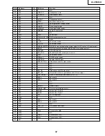
Pin No. Pin Name
I/O
Pin Name
Function
51
P43
O
N.C
52
P42
O
HPMUTE
Headphones mute
53
P41
O
SP MUTE1
Main speaker mute
54
P40
O
N.C
55
P37
I
HP DET
Headphones detect
56
P36
O
SSTBY
Amplifier power control
57
P35
I
VSH IN
Panel gate driver voltage confirm
58
P34
O
LMUTE
Line out audio mute
59
P33
O
V IN/OUT
Video input/output select
60
P32
O
SRESET
Audio IC reset output
61
P31
O
N.C
62
Xcc2
I
Vcc2
Power input
63
P30
O
TCON_OUT_OTL DVP control output control
64
Vss
I
Vss
GND
65
P27
O
V_SEL
AV selector switch
66
P26
O
TV_SEL
AV selector switch
67
P25
O
BUS SELECT(I
2
C)
DVP I2C/4-line communication system select (H: I2C control, L: Serial control)
68
P24
O
MPCE
DVP 4-line serial chip enable (MPCE)/DVP slave address select
69
P23
O
OPCLED
OPC LED light-up
70
P22
O
INV_POW
Separately-excited inverter power control
71
P21
O
VGH
Panel power control
72
P20
O
POWout
DC/DC control output
73
P17
I
ADPPOW
Adaptor ON/OFF input
74
P16
O
DACOUTCON
Gradation control IC output control
75
P15
O
N.C
76
P14
O
N.C
77
P13
O
N.C
78
P12
O
MP_DA
Gradation control IC data output
79
P11
O
MP_CLK
Temperature sensor or gradation control IC clock output
80
P10
O
DDC_RESET
Video IC reset output (Renesas DVP, 3D YC)
81
P07
I
KEY4
Key input 4
82
P06
I
KEY5
Key input 5
83
P05
O
N.C
84
P04
O
N.C
85
P03
O
MODEL
Model ID port
86
P02
I
SHORT_DET
Over-current protection detect
87
P01
I
INCH2
Screen size ID port 2
88
P00
I
INCH1
Screen size ID port 1
89
AN7
I
AFT
AFT voltage input
90
P106
O
N.C
91
AN5
I
KEY1
Key input 1
92
AN4
I
KEY2
Key input 2
93
P103
O
N.C
94
AN2
I
OPC_IN
OPC sensor level input
95
96
AVss
I
AVss
Connected to GND
97
P100
O
N.C
98
VREF
I
VREF
Connected to +3.3V
99
AVcc
I
AVcc
Connected to +3.3V
100
P97
O
N.C
Summary of Contents for LC 13SH4U
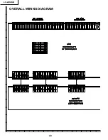
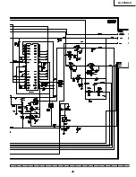
Page 40: ...LC 20SH4U 8 7 10 9 6 5 4 3 2 1 A B C D E F G H 40 OVERALL WIRING DIAGRAM ...
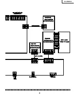
Page 41: ...LC 20SH4U 41 17 16 19 18 15 14 13 12 11 10 ...
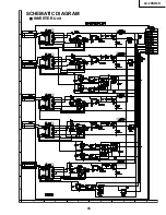
Page 43: ...LC 20SH4U 43 6 5 4 3 2 1 A B C D E F G H SCHEMATIC DIAGRAM Ë INVERTER Unit ...
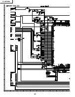
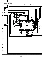
Page 44: ...LC 20SH4U 8 7 10 9 6 5 4 3 2 1 A B C D E F G H 44 ËMAIN Unit 1 4 ...
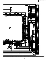
Page 45: ...LC 20SH4U 45 17 16 19 18 15 14 13 12 11 10 ...
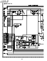
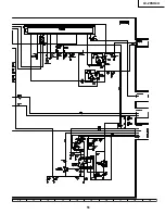
Page 46: ...LC 20SH4U 8 7 10 9 6 5 4 3 2 1 A B C D E F G H 46 ËMAIN Unit 2 4 ...
Page 47: ...LC 20SH4U 47 17 16 19 18 15 14 13 12 11 10 ...
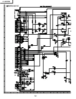
Page 48: ...LC 20SH4U 8 7 10 9 6 5 4 3 2 1 A B C D E F G H 48 ËMAIN Unit 3 4 ...
Page 49: ...LC 20SH4U 49 17 16 19 18 15 14 13 12 11 10 ...
Page 50: ...LC 20SH4U 8 7 10 9 6 5 4 3 2 1 A B C D E F G H 50 ËMAIN Unit 4 4 ...
Page 51: ...LC 20SH4U 51 17 16 19 18 15 14 13 12 11 10 ...
Page 52: ...LC 20SH4U 8 7 10 9 6 5 4 3 2 1 A B C D E F G H 52 ËSUB Unit 1 4 ...
Page 53: ...LC 20SH4U 53 17 16 19 18 15 14 13 12 11 10 ...
Page 54: ...LC 20SH4U 8 7 10 9 6 5 4 3 2 1 A B C D E F G H 54 ËSUB Unit 2 4 ...
Page 55: ...LC 20SH4U 55 17 16 19 18 15 14 13 12 11 10 Note SUB 3 does not use it ...
Page 56: ...LC 20SH4U 8 7 10 9 6 5 4 3 2 1 A B C D E F G H 56 ËSUB Unit 4 4 ...
Page 57: ...LC 20SH4U 57 17 16 19 18 15 14 13 12 11 10 ...
Page 58: ...LC 20SH4U 58 6 5 4 3 2 1 A B C D E F G H ËOPERATION Unit ...
Page 59: ...LC 20SH4U 59 6 5 4 3 2 1 A B C D E F G H Ë R C LED Unit ...
Page 68: ...LC 20SH4U 8 7 10 9 6 5 4 3 2 1 A B C D E F G H 68 ...
Page 69: ...LC 20SH4U 69 17 16 19 18 15 14 13 12 11 10 SUB Unit Wiring Side ...
Page 70: ...LC 20SH4U 8 7 10 9 6 5 4 3 2 1 A B C D E F G H 70 ...
Page 71: ...LC 20SH4U 71 17 16 19 18 15 14 13 12 11 10 SUB Unit Chip Parts Side ...
Page 73: ...LC 20SH4U 73 17 16 19 18 15 14 13 12 11 10 ...
Page 87: ...87 LC 20SH4U PACKING OF THE SET X2 X3 X4 X1 S2 S3 S3 S4 S3 S3 S5 S1 X5 ...

