LC-20SH4U
23
TEST PATTERN IN THE ADJUSTMENT PROCESS MODE
IC1201 (LCD controller) test pattern
1) Getting the test pattern displayed
Call the adjustment process mode, select "DVP" on page 4, and press the ENTER button. Next select "DVP
TEST PATTERN" in line 2 on page 1. (The "DVP TEST PATTERN" turns yellow.) Now use the cursor RIGHT/
LEFT keys to get the test pattern displayed.
To quit the test pattern, enter "0" in the "DVP TEST PATTERN" setting. The test pattern is kept onscreen even
by pressing the RETURN UP/DOWN buttons. The test pattern display is cancelled when the power is turned
off, and the usual display appears instead when the power is turned on again.
2) Test pattern displayed
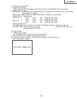
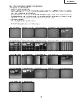
The following test pattern appears onscreen.
»
The DVP test pattern comes in 22 different types.
1 Black & white (Size:Minimum)
2 Black & white (Size:Small)
3 Black & white (Size:Medium)
4 Black & white (Size:Large)
5 Crosshatch (Spacing:Minimum)
6 Crosshatch (Spacing:Small)
7 Crosshatch (Spacing:Medium)
8 Crosshatch (Spacing:Large)
9 Color bar (Spacing:Minimum)
10 Color bar (Spacing:Small)
11 Color bar (Spacing:Medium)
12 Color bar (Spacing:Large)
13 Lamp (Spacing:Small)
14 Lamp (Spacing:Medium)
15 Vertical lamp (Spacing:Small)
16 Vertical lamp (Spacing:Medium)
17 Black-background pattern
18 White 100%
19 White 50%
20 Red-background pattern
21 Green-background pattern
22 Blue-background pattern
Summary of Contents for LC 13SH4U
Page 40: ...LC 20SH4U 8 7 10 9 6 5 4 3 2 1 A B C D E F G H 40 OVERALL WIRING DIAGRAM ...
Page 41: ...LC 20SH4U 41 17 16 19 18 15 14 13 12 11 10 ...
Page 43: ...LC 20SH4U 43 6 5 4 3 2 1 A B C D E F G H SCHEMATIC DIAGRAM Ë INVERTER Unit ...
Page 44: ...LC 20SH4U 8 7 10 9 6 5 4 3 2 1 A B C D E F G H 44 ËMAIN Unit 1 4 ...
Page 45: ...LC 20SH4U 45 17 16 19 18 15 14 13 12 11 10 ...
Page 46: ...LC 20SH4U 8 7 10 9 6 5 4 3 2 1 A B C D E F G H 46 ËMAIN Unit 2 4 ...
Page 47: ...LC 20SH4U 47 17 16 19 18 15 14 13 12 11 10 ...
Page 48: ...LC 20SH4U 8 7 10 9 6 5 4 3 2 1 A B C D E F G H 48 ËMAIN Unit 3 4 ...
Page 49: ...LC 20SH4U 49 17 16 19 18 15 14 13 12 11 10 ...
Page 50: ...LC 20SH4U 8 7 10 9 6 5 4 3 2 1 A B C D E F G H 50 ËMAIN Unit 4 4 ...
Page 51: ...LC 20SH4U 51 17 16 19 18 15 14 13 12 11 10 ...
Page 52: ...LC 20SH4U 8 7 10 9 6 5 4 3 2 1 A B C D E F G H 52 ËSUB Unit 1 4 ...
Page 53: ...LC 20SH4U 53 17 16 19 18 15 14 13 12 11 10 ...
Page 54: ...LC 20SH4U 8 7 10 9 6 5 4 3 2 1 A B C D E F G H 54 ËSUB Unit 2 4 ...
Page 55: ...LC 20SH4U 55 17 16 19 18 15 14 13 12 11 10 Note SUB 3 does not use it ...
Page 56: ...LC 20SH4U 8 7 10 9 6 5 4 3 2 1 A B C D E F G H 56 ËSUB Unit 4 4 ...
Page 57: ...LC 20SH4U 57 17 16 19 18 15 14 13 12 11 10 ...
Page 58: ...LC 20SH4U 58 6 5 4 3 2 1 A B C D E F G H ËOPERATION Unit ...
Page 59: ...LC 20SH4U 59 6 5 4 3 2 1 A B C D E F G H Ë R C LED Unit ...
Page 68: ...LC 20SH4U 8 7 10 9 6 5 4 3 2 1 A B C D E F G H 68 ...
Page 69: ...LC 20SH4U 69 17 16 19 18 15 14 13 12 11 10 SUB Unit Wiring Side ...
Page 70: ...LC 20SH4U 8 7 10 9 6 5 4 3 2 1 A B C D E F G H 70 ...
Page 71: ...LC 20SH4U 71 17 16 19 18 15 14 13 12 11 10 SUB Unit Chip Parts Side ...
Page 73: ...LC 20SH4U 73 17 16 19 18 15 14 13 12 11 10 ...
Page 87: ...87 LC 20SH4U PACKING OF THE SET X2 X3 X4 X1 S2 S3 S3 S4 S3 S3 S5 S1 X5 ...


