LC-20SH4U
31
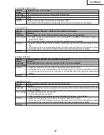
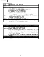
Table of Key Functions in Sound Only Mode
Key
Functions
Sound only mode setup process
Sound only mode process
Special reset key
»
Mute cleared.
»
Backlight on.
BACKLIGHT
»
Message deleted.
»
Backlight error detect on.
»
BACKLIGHT mode turned on.
Sound only mode clear guide message
(Sound only mode ended)
displayed.
(Current BACKLIGHT mode status displayed)
Released key
»
Mute cleared.
»
Backlight on.
»
Message deleted.
»
Backlight error detect on.
»
BACKLIGHT mode turned on.
»
Mute cleared
(Sound only mode ended)
»
BACKLIGHT mode turned on.
(Sound only mode ended)
Temporary reset key
»
BACKLIGHT mode temporarily turned on
»
BACKLIGHT mode temporarily turned on
(Externally OFF).
(Externally OFF).
»
Message deleted.
»
Backlight on.
»
Description of pressed key displayed for 3
»
Backlight error detect on.
seconds.
»
Description of pressed key displayed for 3
»
Sound only mode setup message displayed.
seconds.
(Current BACKLIGHT mode status displayed)
»
Sound only mode setup message displayed.
(Current BACKLIGHT mode status displayed)
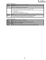
Table of Key Allocation in Sound Only Mode (Unit keys/Remote control keys)
Unit keys
Remote control
Key
POWER
INPUT
MENU
CH
VOL
POWER
PIC.FLIP
DISPLAY
SLEEP
MENU
CURSOR
ENTER
BACKLIGHT
MUTE
MTS
INPUT
VOL
AUDIO ONLY
CH
FLASHBACK
CH1~10/0
CH100
CLOSED CAPTION
AV MODE
MENU RETURN
Allocation
Released
Temporary reset
Released
Temporary reset
Temporary reset
Released
Released
Temporary reset
Temporary reset
Released
Released
Released
Special reset
Temporary reset
Temporary reset
Temporary reset
Temporary reset
Released
Temporary reset
Temporary reset
Temporary reset
Temporary reset
Temporary reset
Released
Released
* When the VOLUME FIXED, INPUT MODE FIXED or other fixed status is set up, this status is given priority.
Summary of Contents for LC 13SH4U
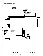
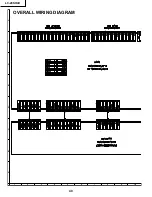
Page 40: ...LC 20SH4U 8 7 10 9 6 5 4 3 2 1 A B C D E F G H 40 OVERALL WIRING DIAGRAM ...
Page 41: ...LC 20SH4U 41 17 16 19 18 15 14 13 12 11 10 ...
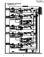
Page 43: ...LC 20SH4U 43 6 5 4 3 2 1 A B C D E F G H SCHEMATIC DIAGRAM Ë INVERTER Unit ...
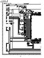
Page 44: ...LC 20SH4U 8 7 10 9 6 5 4 3 2 1 A B C D E F G H 44 ËMAIN Unit 1 4 ...
Page 45: ...LC 20SH4U 45 17 16 19 18 15 14 13 12 11 10 ...
Page 46: ...LC 20SH4U 8 7 10 9 6 5 4 3 2 1 A B C D E F G H 46 ËMAIN Unit 2 4 ...
Page 47: ...LC 20SH4U 47 17 16 19 18 15 14 13 12 11 10 ...
Page 48: ...LC 20SH4U 8 7 10 9 6 5 4 3 2 1 A B C D E F G H 48 ËMAIN Unit 3 4 ...
Page 49: ...LC 20SH4U 49 17 16 19 18 15 14 13 12 11 10 ...
Page 50: ...LC 20SH4U 8 7 10 9 6 5 4 3 2 1 A B C D E F G H 50 ËMAIN Unit 4 4 ...
Page 51: ...LC 20SH4U 51 17 16 19 18 15 14 13 12 11 10 ...
Page 52: ...LC 20SH4U 8 7 10 9 6 5 4 3 2 1 A B C D E F G H 52 ËSUB Unit 1 4 ...
Page 53: ...LC 20SH4U 53 17 16 19 18 15 14 13 12 11 10 ...
Page 54: ...LC 20SH4U 8 7 10 9 6 5 4 3 2 1 A B C D E F G H 54 ËSUB Unit 2 4 ...
Page 55: ...LC 20SH4U 55 17 16 19 18 15 14 13 12 11 10 Note SUB 3 does not use it ...
Page 56: ...LC 20SH4U 8 7 10 9 6 5 4 3 2 1 A B C D E F G H 56 ËSUB Unit 4 4 ...
Page 57: ...LC 20SH4U 57 17 16 19 18 15 14 13 12 11 10 ...
Page 58: ...LC 20SH4U 58 6 5 4 3 2 1 A B C D E F G H ËOPERATION Unit ...
Page 59: ...LC 20SH4U 59 6 5 4 3 2 1 A B C D E F G H Ë R C LED Unit ...
Page 68: ...LC 20SH4U 8 7 10 9 6 5 4 3 2 1 A B C D E F G H 68 ...
Page 69: ...LC 20SH4U 69 17 16 19 18 15 14 13 12 11 10 SUB Unit Wiring Side ...
Page 70: ...LC 20SH4U 8 7 10 9 6 5 4 3 2 1 A B C D E F G H 70 ...
Page 71: ...LC 20SH4U 71 17 16 19 18 15 14 13 12 11 10 SUB Unit Chip Parts Side ...
Page 73: ...LC 20SH4U 73 17 16 19 18 15 14 13 12 11 10 ...
Page 87: ...87 LC 20SH4U PACKING OF THE SET X2 X3 X4 X1 S2 S3 S3 S4 S3 S3 S5 S1 X5 ...

