background image

EXTERNAL UNIT CONNECTION

Cords required to connect an external unit

The following cords are available to connect an external unit.

Cord included with this unit

Optical digital cable

Coaxial digital cord

Optional cord

Video cord

RCA cord

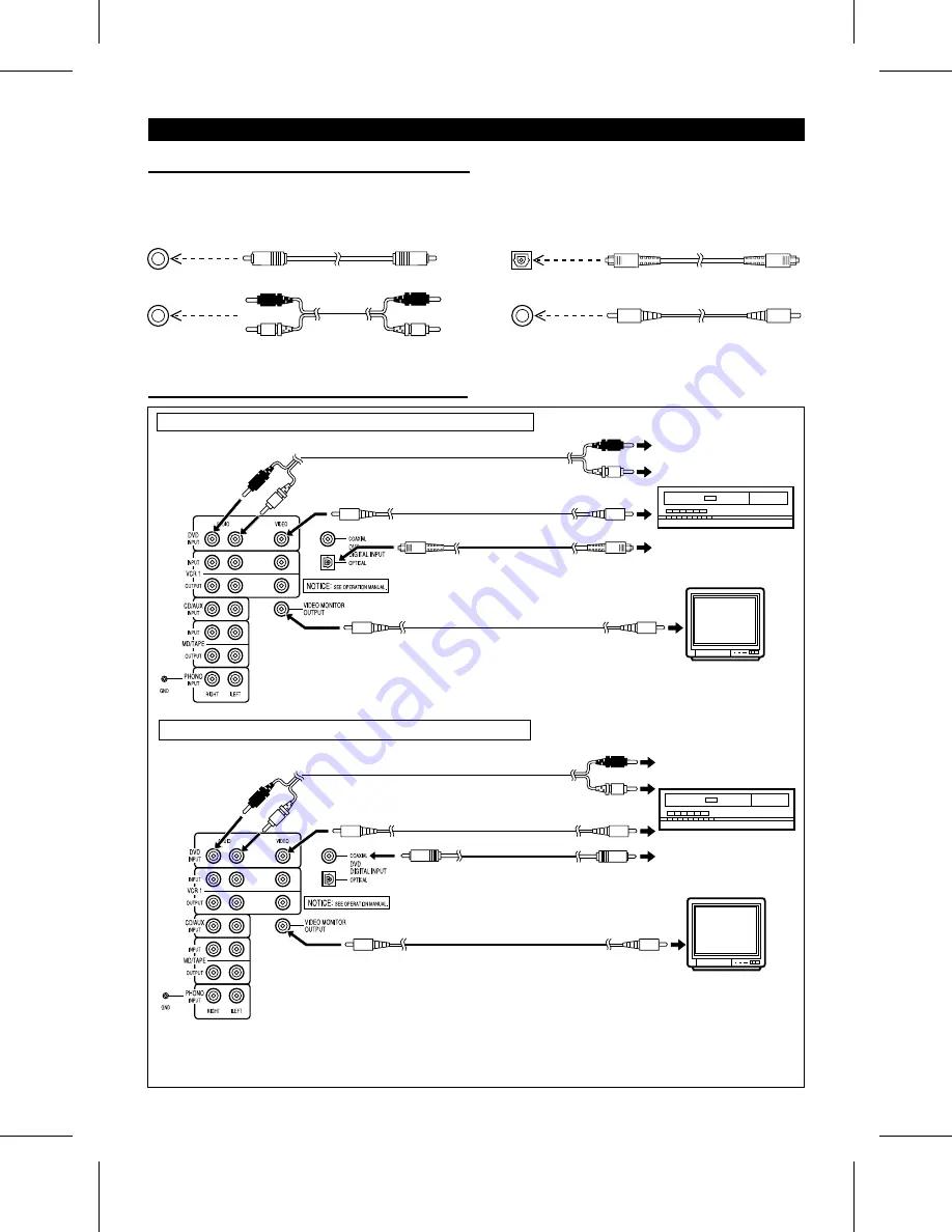
When connecting the unit to a DVD player

When connecting an audio signal using an optical digital cable

To the audio (line) output jacks

TV

To the video output jack

To the video input jack

To the audio (digital) output jack

DVD player

When connecting an audio signal using a coaxial digital cord

To the video input jack

TV

To the video output jack

To the audio (line) output jacks

To the audio (digital) output jack

DVD player

Caution: A DVD player allows you to select the "PCM" or "DOLBY DIGITAL" audio output mode. Before playing a Dolby

digital sound disc, be sure to set the unit in the "DOLBY DIGITAL" mode. For more details, see the operation
manual for your DVD player.

HT-DD5000(SEC) TINSE0009SJZZ

8

Summary of Contents for HT-DD5000

Page 1: ... if not installed and used in accordance with the instructions may cause harmful interference to radio communications However there is no guarantee that interference will not occur in a particular installation If this equipment does cause harmful interfer ence to radio or television reception which can be determined by turning the equipment off and on the user is encouraged to try to correct the i...

Page 2: ...h its proper ventilation For ex ample the appliance should not be situated on a bed sofa rug or similar surface that may block the ventilation openings or placed in a built in installation such as a bookcase or cabinet that may impede the flow of air through the ventilation openings 7 Heat The appliance should be situated away from heat sources such as radiators heat registers stoves or other appl...

Page 3: ...rates electrical noise Hold the AC power plug by the head when removing it from the AC outlet since pulling the cord can damage internal wires Do not remove the outer cover as this may result in electric shock Refer internal service to your local SHARP service facility Use the unit on a firm level surface free from vibration and do not place anything on the top of the unit If ERROR appears or no s...

Page 4: ...e to the CENTER SPEAKER terminals as shown Use a speaker with an impedance of 8 ohms or more as a lower impedance speaker can damage the unit Connect the black wire with the white line to the negative terminal and the black wire to the positive termi nal Wires to be used with each speaker Connecting the speaker wires 1 Hold the speaker wire release catch down 2 Insert the wire into the speaker ter...

Page 5: ...lack wire with the white line to the negative terminal and the black wire to the positive termi nal Caution Do not reverse the right channel and left channel wires when connecting the speakers to the unit Do not let bare speaker wires touch each other as this may damage the amplifier and or speakers Do not allow any objects to fall into or to be placed in the bass reflex openings Do not stand or s...

Page 6: ...d The front speakers and sub woofer may be used by the sides of the TV The center speaker may be used on top of the TV However some color variation may occur depending on the type of TV used If color variations occur Turn off the TV from the power switch After 15 30 min utes turn the TV on again If the color variation is still present Move the speakers further away from the TV Surround left Sub wo...

Page 7: ...e batteries nickel cadmium battery etc Notes concerning use Replace the batteries if the operating distance is reduced or if the operation becomes erratic Periodically clean the transmitter LED on the remote con trol and the sensor on the main unit with a soft cloth Exposing the sensor on the main unit to strong light may interfere with operation Change the lighting or the direc tion of the unit K...

Page 8: ...the AM loop antenna and the FM antenna wire away from the unit for better reception If the antenna wires are placed near the AC power cord they may cause interference Outdoor FM antenna Use an outdoor FM antenna 75 ohm coaxial cable if you require better reception Consult your dealer Note When an outdoor FM antenna is used disconnect the sup plied FM antenna wire from the FM 75 OHMS terminal Outdo...

Page 9: ...put jacks TV To the video output jack To the video input jack To the audio digital output jack DVD player When connecting an audio signal using a coaxial digital cord To the video input jack TV To the video output jack To the audio line output jacks To the audio digital output jack DVD player Caution A DVD player allows you to select the PCM or DOLBY DIGITAL audio output mode Before playing a Dolb...

Page 10: ...k or an MD deck To the audio output jacks To the audio input jacks To the video input jack TV VCR To the video output jack To the video input jack MD deck To the audio output jacks To the audio input jacks To the audio output jacks To the video output jack VCR Camcorder HT DD5000 SEC TINSE0009SJZZ 9 ...

Page 11: ...CD AUX button To select the unit connected to the MD TAPE jacks Press the MD TAPE button To select the unit connected to the PHONO jacks Press the PHONO button Note When a function other than DVD VCR 1 or VCR 2 is se lected the video monitor output is not available POWER STAND BY POWER How to turn the power on or off 1 Set the POWER button on the main unit to ON The STAND BY indicator will light u...

Page 12: ...he SPEAKERS A button to ON Sound will also be heard from the center sub woofer and surround speakers To listen using the B speakers Set the SPEAKERS B button to ON No sound will be heard from the center sub woofer or surround speakers To listen using both the A and B speakers Set the SPEAKERS A and B buttons to ON To stop the sound from all of the speakers Set the SPEAKERS A and B buttons to OFF T...

Page 13: ... 1 FLAT HEAVY 1 HEAVY 2 SOFT 2 SOFT 1 FLAT The sound is not modified HEAVY 1 Bass and treble are slightly emphasized HEAVY 2 Bass and treble are emphasized more SOFT 1 Treble is cut a little SOFT 2 Treble is reduced a lot Note When the equalizer mode is being used the Dolby Pro Logic Surround mode is canceled Sub woofer output level Remote control operation When the SUB WOOFER LEVEL W X button is ...

Page 14: ...t L R surround L R Center only monaural Front L R center Front L R When the surround mode is set to Normal Phantom or Wide sound will also be heard from the surround speakers Front L R center surround monaural Front L R surround monaural Front L R center surround L R DIGITAL DIGITAL DIGITAL DIGITAL DIGITAL DIGITAL DIGITAL If a low frequency sound effect Low Frequency Effect contains a Dolby digita...

Page 15: ...he video software program STEREO NORMAL WIDE PHANTOM Remote control operation 3 Press the DOLBY SURROUND button 4 Within 3 seconds press the DOLBY SURROUND button repeatedly to select the Dolby Pro Logic Surround mode 5 Play the video software program Note When the Normal Phantom Wide mode is being used the equalizer will be set to FLAT STEREO NORMAL WIDE PHANTOM SURROUND EFFECT CONTROL This produ...

Page 16: ... rear signals will be mixed and output from the front speakers For a Dolby digital 1 0 input monaural sound will be out put from the front speakers Preset balance Remote control operation While you are listening to music in any of the Dolby Pro Logic Surround modes NORMAL PHANTOM WIDE you can change the apparent position of the sound coming from the speakers to any position which has been stored i...

Page 17: ... is se lected the indicator for that speaker position will go out 6 Within 10 seconds press the ITEM button to make SURR SP appear The surround speaker indicators will flash 7 Within 10 seconds press the SET UP W or X button to select SP YES or SP NO YES When the speakers are connected NO When no speaker is connected When NO is selected the indicator for that speaker position will go out 8 Within ...

Page 18: ...center speaker SURR SP To delay the sound from the surround speakers The selected speaker indicator s will flash 3 Within 10 seconds press the SET UP W or X button to select a value Adjustable range CENTER 0 ms 5 ms SURROUND 0 ms 15 ms When the DIGITAL indicator is lit 15 ms 30 ms When the DIGITAL indicator is not lit Can be changed in 1 ms steps Notes As a guide for setting the correct delay time...

Page 19: ...ged within a range of 1 to 20 Note The surround speaker balance will not be changed To balance the front speaker s In step 3 press the SET UP W or X button to make F SP CEN appear Speaker level setting The output level of the center surround or sub woofer speak ers can be adjusted 1 Press the MENU button repeatedly to make SP LEVEL appear 2 Within 10 seconds press the ITEM button repeatedly to sel...

Page 20: ...ard until the current menu selec tion is changed by pressing the MENU button again or by selecting some other function 3 To adjust the speaker level while the test tone is being output from a particular speaker press the SET UP W or X button The speaker level can be adjusted within a range of 10dB to 10dB in 1dB steps Notes If NO is selected for any individual speaker s size setting page 16 the te...

Page 21: ...econds press the ITEM button to select MAX STD or MIN MAX This setting does not compress the dynamic range of the Dolby digital signal allowing you to enjoy the full powerful sound of Dolby encoded digital signals STD This setting compresses the dynamic range and may produce a more appropriate volume range for home use MIN This setting compresses the dynamic range allow ing you to enjoy movies at ...

Page 22: ...to scan tuning may stop automatically at that point If a weak station signal is found during auto scan tuning the station will be skipped To stop auto tuning press the TUNING UP or DOWN button again 5 To receive an FM stereo transmission press the TUNER BAND button so that the STEREO indicator on the display lights up j will appear when an FM broadcast is in stereo 6 If the FM reception is weak pr...

Page 23: ...ar in the display in numerical order irrespective of the frequency bands Note When searching for a memorized station do not press the PRESET button for more than 0 5 seconds When the PRESET button is pressed for more than 0 5 sec onds the unit will enter the preset memory scan mode Backup function The backup function protects all station presets for a few hours should there be a power failure or t...

Page 24: ...ed off and timer play back will not work 8 When the timer start time is reached timer playback will start The volume will increase gradually until it reaches the volume you were listening to before turning off the unit Even if you selected a different function other than the tuner before turning off the power the tuner will be se lected 9 The power will be turned off one hour after the timer has s...

Page 25: ...l the sleep operation Press the POWER button to turn the power off Notes After the sleep operation has finished the sleep setting time will be canceled If you want to set the sleep oper ation again start from the beginning of this procedure The sleep operation cannot control any components that are connected to the DVD VCR 1 VCR 2 CD AUX MD TAPE or PHONO jacks HEADPHONES Before plugging in or unpl...

Page 26: ...fects sub woofer Matrix processing Dolby Surround Sound processing Discrete processing Dolby digital encoding decoding 16 bits Number of signal processing bits 20 bits 7 kHz Surround Sound high frequency playback limit 20 kHz L S C R S L S W L S C R R S Dolby Surround This is the encoding decoding system for general purpose Dolby Surround When the sound from films recorded in Dolby Surround are re...

Page 27: ...minals Front speakers 8 ohms Center speaker 8 ohms Surround speakers 8 ohms Sub woofer 8 ohms Headphones 16 50 ohms recommended 32 ohms Input terminals DVD VCR 1 VCR 2 CD AUX MD TAPE 500 mV 47 kohms PHONO 3 5 mV 47 kohms Tuner section Frequency range FM 87 5 108 MHz AM 530 1 720 kHz Front speaker section Type 2 way 6 5 16 16 cm woofer and 2 5 cm tweeter Maximum input power 80 W Impedance 8 ohms Di...

Page 28: ... exclusive remedy available to the purchaser Correction of defects in the manner and for the period of time described herein shall constitute complete fulfillment of all liabilities and responsibilities of Sharp to the purchaser with respect to the Product and shall constitute full satisfaction of all claims whether based on contract negligence strict liability or otherwise In no event shall Sharp...

Reviews: