2-2. Optical adjust plate
1. General
This procedure defines the in-field adjustment method for the FO-
6500 series scanner optical system – CCD, lenses, mirrors, etc. –
which may be required when the optical system is removed for servic-
ing. This adjustment needs the use of a special in-field scanner opti-
cal sysem adjusing tool and a dual beam oscilloscope.
2. Adjustment
1) Remove the left cabinet, scanner front cover, inner tray, and
printer front cover. As shown in Fig. 6, incline the scanner unit.
2) Connect the oscilloscope as follows: –
CH1 to video signal (AVO) on control board
CH2 to sync signal (PHIT) on control board
GND to test point ground (DG) on control board.
3) Turn machine power on.
4) Select the optical adjust mode of diagnostics then press the
START/COPY key.
5) Open Operation Panel. Then unit the optical adjustment tool on
the lower document guide. (Fig. 7)
6) Remove the lock paint of CCD board holding screws. Then loosen
one screw at a time and adjust the location of the CCD board so
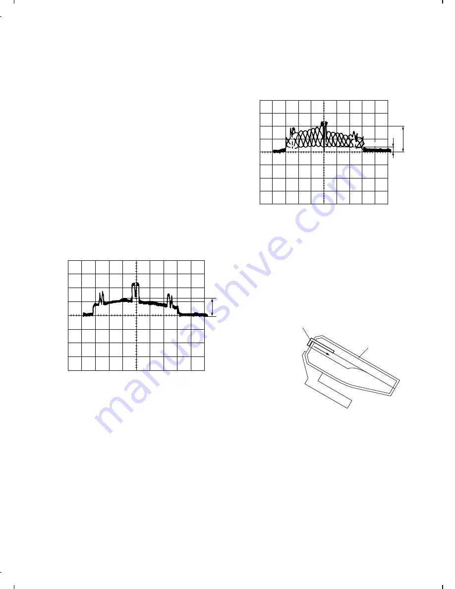
that the CCD output is as shown in Fig. 2. Also ensure that the
centre black level trough is delayed 528
µ
sec from the trigger sync
signal
φ
T (PHIT).
See Fig. 5.
0.1msec/Div
100mV/Div
Maximum
Fig. 1
Note: Above shows correct CCD output but focus need adjusting as
in step 8.
7) If after adjusting CCD output in step 6) scope reads the same as in
Fig. 2 run a test copy. (Focus should be OK)
Note: If the lens and lens holder have not been moved. You may skip
step 8.
8) Remove the lock paint of lens. Adjust the location of the lens so
that the difference between A and B of CCD output should be the
largest, then secure the lens on that position. The output signal
waveform must be symmetrical. After it ha been complete, secure
the screws with the lock paint. with this, lens focus adjustment is
complete. (Fig. 2)
0.5msec/Div
500mV/Div
A
B
GND
White level
Black level
Fig. 2
9) Press STOP key again after completion of the adjustments. The
mode is shifted to the diagnostic STANDBY MODE.
Notes:
1) Adjust the optical adjustment tool in the slant state as shown in
Fig. 6. After the adjustment, the waveform will slightyl vary if it is
stood up as shown in Fig. 8.
2) Use the optical adjustment tool by pressing it in the arrow direc-
tion. If it is floated, the proper adjustment is impossible. (Fig. 3)
Scanner Unit
Optical adjustment tool
Fig. 3
FO-4500H
8 – 4
Summary of Contents for FO-4500
Page 16: ...M E M O FO 4500H 1 14 ...
Page 129: ...Control PWB parts layout Top side 6 11 FO 4500H ...
Page 130: ...Control PWB parts layout Bottom side 6 12 FO 4500H ...
Page 133: ...TEL LIU PWB parts layout 6 15 FO 4500H ...
Page 134: ...6 16 FO 4500H ...
Page 136: ...Power supply PWB parts layout 6 18 FO 4500H ...
Page 141: ...M E M O 6 23 FO 4500H ...
Page 149: ...Scanner unit Fig 6 Optical adjustment tool Fig 7 Fig 8 FO 4500H 8 6 ...


