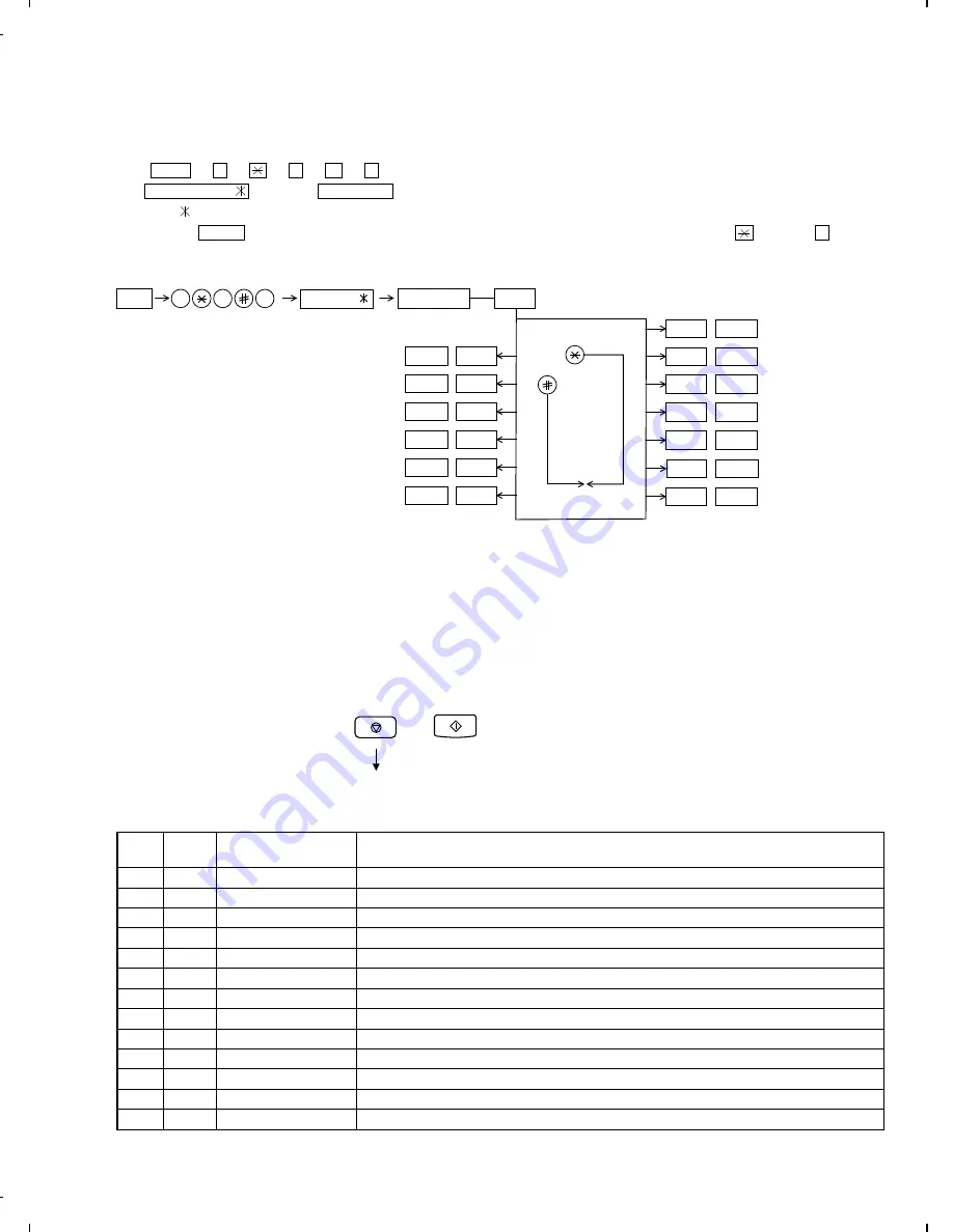
[2] Diagnostics and service soft switch
2. Diagnostic items
ITEM
No.
DIRECT
key
Contents
Function
1
1
SOFT SWITCH MODE
Soft switches are displayed and changed. List can be output.
2
2
ROM & RAM CHECK
ROM is sum-checked, and RAM is matched. Result list is output.
3
3
AGING MODE
10 sheets of check patterns are output every 5 minutes per sheet.
4
4
PANEL KEY TEST
Panel keys are tested.
5
5
CHECK PATTERN
Check pattern is output.
6
6
SIGNAL SEND MODE
Various signals of FAX communication are output.
7
7
MEMORY CLEAR
Back-up memory is cleared, and is set at delivery.
8
8
CCD ADJUST MODE
Optical system is adjusted.
9
9
ALL BLACK PRINT
To check the print head, whole dots are printed over the interval of 2 m.
10
10
AUTO FEEDER MODE
Insertion and discharge of document are tested.
11
11
ENTRY DATA SEND
Registered content is sent.
12
12
ENTRY DATA RECEIVE
Registered content is received, and its list is output.
13
13
RS232C CHECK
Checks RS232C interface box.
1. Operating procedure
(1) Entering the diagnostic mode
Press FUNC
→
9
→
→
8
→
#
→
7 , and the following display will appear.
ROM Ver. FHH0
After 2 sec: DIAG MODE
FHH0
Then press the START key and country name selected by country select will appear. Select the desired item with the key or the # key
or select with the rapid key. Enter the mode with the START key.
(Diag
•
specifications)
FUNC
Ver. FHH0
DIAG MODE
9
8
7
START
1
Soft switch mode
START
2
ROM & RAM check
START
3
Aging mode
START
4
Panel key test
START
5
Check pattern
START
6
Signal send mode
START
START
KEY
STOP
KEY
+
+
"Power ON"
Memory clear
(Work + Backup)
"Power ON" and keep the STOP key pressed
while "WAIT A ...." is indicated.
Press the START key when "MEMORY CLEAR?" appears.
START
12
START
11
All black print
START
10
Auto feeder mode
START
9
Entry data send
Entry data receive
CCD adjust mode
START
8
Memory clear
START
7
START
13
RS232C check
If the dial mode cannot be set, repeat the dial mode operation, per-
forming the following operation.
After the power is turned on and "WAIT A MOMENT" is indicated,
press the STOP key.
UX-600MU/MC
FO-1660U/C
2 – 2
Summary of Contents for FO-1660
Page 15: ...M E M O UX 600MU MC FO 1660U C 1 13 ...
Page 72: ...Control PWB parts layout Top side 6 8 UX 600MU MC FO 1660U C ...
Page 73: ...Control PWB parts layout Bottom side 6 9 UX 600MU MC FO 1660U C ...
Page 75: ...TEL LIU PWB parts layout 6 11 UX 600MU MC FO 1660U C ...
Page 77: ...6 13 Power supply PWB parts layout UX 600MU MC FO 1660U C ...
Page 80: ...Operation panel PWB parts layout 6 16 UX 600MU MC FO 1660U C ...
Page 92: ...M E M O UX 600MU MC FO 1660U C 8 8 ...
Page 115: ......


