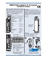
EL-2631L/2615P BLOCK DIAGRAM
– 2 –
1. BLOCK DIAGRAM
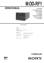
2. POWER VOLTAGE
Measure with the AC input voltage rating.
■
■
■
■
MEASURING PIN POSITION
3. INK RIBBON REPLACEMENT
1.
Remove the paper roll from the calculator. (Tear the paper and
remove it from the print mechanism by using
.)
2.
Turn the power off before replacing ribbon.
3.
Remove the printer cover by sliding it towards the back of the calcu-
lator. (Fig.1)
Fig.1
4.
Remove the old ribbon by pulling it up.
5.
Insert the new ribbon.
6. With the black side of the ribbon facing upwards, place one of the
reels on the reel shaft on the right. (Fig.2) Make sure that the reel is
securely in place.
Fig.2
7. Thread the ribbon around the outside of the metal guides. (Fig.3)
Fig.3
8. Take up any slack by manually turning one of the reels.
9. Replace the printer cover.
10. Replace the paper roll.
Printer driver
AC
transformer
Power supply
circuit
Display tube
LSI
Key
slide switch
Printer
Power supply line
Signal line
AC input
Measurement position
Power voltage
VF-VF
4.2Vac ~ 5.1Vac
VSS-VCC
5.7V ~ 6.6V
(*1)VL-VPR
14V ~ 16V
(*1): Measurement of VL-VPR voltage must be performed with the
PAPER FEED key being pressed.
VPR
VF
VF
VSS
VL
VCC