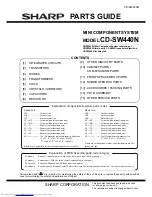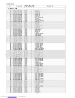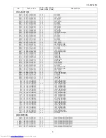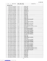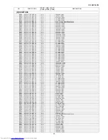
PARTS GUIDE
CD-SW440N
Parts marked with "
" are important for maintaining the safety of the set. Be sure to replace these parts with specified
ones for maintaining the safety and performance of the set.
!
This document has been published to be used
for after sales service only.
The contents are subject to change without notice.
SHARP CORPORATION
MINI COMPONENT SYSTEM
CD-SW440N
MODEL
CD-SW440N Mini Component System consisting of
CD-SW440N (main unit), CP-S440N (speaker system) and
CP-SW440N (subwoofer).
CONTENTS
[1]
INTEGRATED CIRCUITS
[2]
TRANSISTORS
[3]
DIODES
[4]
TRANSFORMERS
[5]
COILS
[6]
CRYSTALS / VIBRATORS
[7]
CAPACITORS
[8]
RESISTORS
[9]
OTHER CIRCUITRY PARTS
[10] CABINET PARTS /
CD MECHANISM PARTS
[11] FRONT SPEAKER BOX PARTS
[12] SUBWOOFER BOX PARTS
[13] ACCESSORIES / PACKING PARTS
[14] P.W.B. ASSEMBLY
[15] OTHER SERVICE PARTS
Explanation of PWB Assembly parts code category
S Category
-- Repair ( Component parts of PWB can be replace and repair, PWB no supply )
X Category
-- Replacement ( PWB can not be repair. Component parts no supply )
S.X Category -- Repair and Replacement ( PWB can repair and replace )
KG Category -- Revolve repair by Business Center ( Return to Business Center and repair by manufacturer. Component parts no supply )
Explanation of capacitors/resistors parts codes
Capacitors
VCC ....................... Ceramic type
VCK ........................ Ceramic type
VCT ........................ Semiconductor type
VC • • MF ............... Cylindrical type (without lead wire)
VC • • MN ............... Cylindrical type (without lead wire)
VC • • TV ................ Square type (without lead wire)
VC • • TQ ............... Square type (without lead wire)
VC • • CY ............... Square type (without lead wire)
VC • • CZ ............... Square type (without lead wire)
VC • • • • • • • • • J .. The 13th character represents capacity difference.
("J" ±5%, "K" ±10%, "M" ±20%, "N" ±30%,
"C" ±0.25 pF, "D" ±0.5 pF, "Z" +80-20%.)
If there are no indications for the electrolytic capacitors, error is ±20%.
Resistors
VRD ....................... Carbon-film type
VRS ........................ Carbon-film type
VRN ....................... Metal-film type
VR • • MF ............... Cylindrical type (without lead wire)
VR • • MN ............... Cylindrical type (without lead wire)
VR • • TV ................ Square type (without lead wire)
VR • • TQ ............... Square type (without lead wire)
VR • • CY ............... Square type (without lead wire)
VR • • CZ ............... Square type (without lead wire)
VR • • • • • • • • • J .. The 13th character represents error.
("J" ±5%, "F" ±1%, "D" ±0.5%.)
If there are no indications for other parts, the resistors are ±5%
carbon-film type.
Summary of Contents for CD-SW440N
Page 19: ...CD SW440N 6 3 Figure 6 2 MAIN SCHEMATIC DIAGRAM 2 6 7 8 9 10 11 12 ...
Page 22: ...CD SW440N 6 6 Figure 6 5 MAIN SCHEMATIC DIAGRAM 5 6 TO SERVO PWB 7 8 9 10 11 12 ...
Page 23: ...CD SW440N 6 7 Figure 6 6 MAIN SCHEMATIC DIAGRAM 6 6 L CH R CH 13 14 15 16 17 18 ...
Page 27: ...CD SW440N 6 11 Figure 6 10 DISPLAY TAPE SCHEMATIC DIAGRAM 2 2 7 8 9 10 11 12 ...
Page 29: ...CD SW440N 6 13 Figure 6 12 DISPLAY TAPE SCHEMATIC DIAGRAM 2 2 7 8 9 10 11 12 ...
Page 37: ...CD SW440N 6 21 Figure 6 20 iPod SCHEMATIC DIAGRAM 2 2 7 8 9 10 11 12 ...
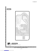
Page 43: ...CD SW440N 6 27 Figure 6 26 WIRING SIDE OF MAIN PWB BOTTOM VIEW 2 2 JP24 7 8 9 10 11 12 ...
Page 45: ...CD SW440N 6 29 MEMO ...
Page 49: ...CD SW440N 6 33 Figure 6 31 WIRING SIDE OF DISPLAY TAPE PWB BOTTOM VIEW 2 2 7 8 9 10 11 12 ...

