


CD-BK3200V
– 10 –
Figure 10-1
Figure 10-2
Figure 10-3
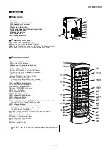
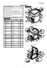
1
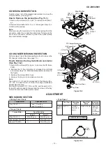
Top Cabinet
1. Screw ................. (A1) x5
9-1
2
Side Panel
1. Screw ................ (B1) x10
9-1
(Left/Right)
2. Hook .................. (B2) x2
3
Rear Panel with
1. Screw ................. (C1) x2
9-2
Fan Motor
2. Screw ................. (C2) x9
3. Screw ................. (C3) x2
4. Socket ................ (C4) x1
4
CD Changer Unit
1. Socket ................ (D1) x4
9-2
2. Hook ................... (D2) x2
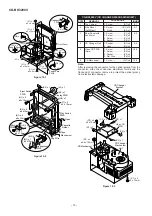
5
Video CD PWB
1. Screw ................. (P1) x4
10-3
(Note)
2. Screw ................. (P2) x4
3. Socket ................ (P3) x4
4. Flat Wire ............. (P4) x2
6
CD Mechanism
1. Screw ................. (Q1) x4
10-3
STEP
REMOVAL
PROCEDURE
FIGURE
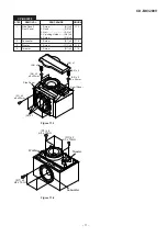
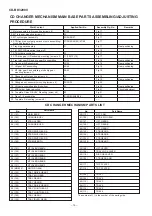
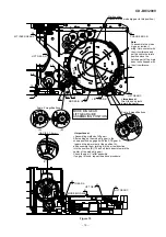
CD-BK3200V (CD CHANGER MECHANISM UNIT)
Note:
After removing the connector for the optical pickup from the
connector, wrap the conductive aluminium foil around the
front end of connector remove to protect the optical pickup
from electrostatic damage.
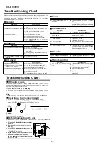
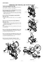
Power Amp.
PWB
(F1) x 2
ø3 x 8mm
(F1) x 2
ø3 x 10mm
(F2)x1
(F2) x 1
Front Panel
(F4) x 1
(F1) x 1
ø3 x 10mm
(G1) x 2
ø3 x 8mm
Push
(F4) x 1
Push
(F1) x 1
ø3 x 10mm
Pull
(G2) x 1
Pull
(G2) x 1
Headphones
PWB
(F3) x 1
Push
Push
(K3) x 1
(K1) x 1
Display PWB
Play Switch
PWB
Open
Cassette
Holder
(H2) x 1
(N1) x 6
ø3 x 10mm
Tape
Mechanism
(H1) x 2
ø3 x 10mm
(J1) x 2
ø3 x 10mm
Eject Switch
PWB
Lug Wire
Headphones
PWB
Mic
PWB
(M1) x 1
ø3 x 10mm
(L1) x 1
ø3 x 10mm
(L2) x 1
(M2) x 1
(K2) x 9
ø3 x 10mm
(K4) x 1
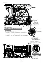
(P2) x 4
ø3 x 10mm
(P1) x 4
ø3 x 14mm
(P4) x 1
(P3) x 1
(P3) x 1
(P4) x 1
(P3) x 2
Video CD
PWB
(Q1) x 4
ø2.6 x 10mm
CD Changer
Mechanism
Unit
CD Changer
Bracket
CD Mechanism