background image

AR-5316/5320 ELECTRICAL SECTION 13-2

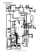
3. Actual wiring diagram

ACTUAL WIRING DIAGRAM 1/7

B03P-VL

(WHITE)

B4B-PH-K-BL

(BLACK)

SPF GROUND WIRE

ORIGINAL TRAY HARNESS

SENSOR HARNESS

04FE-BT-VK-N

(WHITE)

B3B-PH-K-R

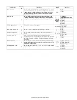
(RED)

Mirror HP

SENSOR

OPTICAL BASE PLATE

CCD PWB

Mirror MOTOR

COPY LAMP

THERMISTER

Side Cover SW

MAIN

MOTOR

TONER

MOTOR

DEV UN

POWER PWB

MCU-PWB

HAND PAPER PICK

UP SOLENOID

HAND PAPER EMPTY

SENSOR

TC

CASETTE EMPTY

SENSOR

PS SOL

GP1S58(C)

GP1S58(O)

2nd CASETTE

(O) Normal Open  :Low

  (C) Normal Close :High

GRID

MC

MCFB

BC

HVU

Bias

SPF UN

USB1.1

IEEE1284

PAPER IN

SENSOR

PICK UP SOL

FUSER

AC Cord

AC SW

HEATER LAMP

REACTOL

230V  ONLY

POLYGON

MOTOR

LSU

APC-PWB

BD-PWB

COOLING FUN

I/F

FFC

FFC

FFC

FFC

FFC

FFC

Front Cover SW

SRU

CASETTE SWITCH

SENSOR

B3B-PH-K-S

(WHITE)

B3B-PH-K-R

(RED)

SUB-D 25

FE4-32-S1505

(BLACK)

B4B-PH-K-S

(WHITE)

08FE-BT-VK-N

(WHITE)

B2P-VH

(WHITE)

B3P-VH

(WHITE)

B3B-PH-K-S

(WHITE)

B20B-PHDSS-B

(WHITE)

B3B-PH-K-BK

(BLACK)

B4B-PH-K-S

(WHITE)

B2B-XH-A-S

(WHITE)

B2B-XH-A-BK

(BLACK)

B2B-XH-A-R

(RED)

B4B-PH-K-R

(RED)

B12B-PHDSS-B

(WHITE)

B26B-PHDSS-B

(WHITE)

35FE-BT-VK-N

(WHITE)

13FE-BT-VK-N

(WHITE)

B7B-PH-K-S

(RED)

B18B-PHDSS-B

(WHITE)

B4B-PH-K-S

(WHITE)

3P TERMINAL

230V  ONLY

B4B-PH-K-S

(WHITE)

35FE-BT-VK-N

(WHITE)

DRUM INISAL SW

B3B-PH-K-BK

(BLACK)

B3B-PH-K-S

(WHITE)

SHIFTER 

MOTOR

GP1A71A1(O)

SHIFTER HP

SENSOR

COOLING

FUN

COOLING

FUN

13FE-BT-VK-N

(WHITE)

MODEL W/O SHIFTER

MODEL WITH SHIFTER

B3B-PH-K-SX

2

(WHITE)

COOLING

FUN

COOLING

FUN

COPY OP PWB

OPERETION PANEL

IMSA-9610S-

24C

(BLACK)

Option

B6B-PH-K-S

(WHITE)

PAPER OUT

SENSOR

DUP

SENSOR

24FMN-BTRK-A

(BLACK)

3

*

[13]ELECTRICALSECTION.fm  2 ページ  2003年12月19日 金曜日 午後3時27分

Summary of Contents for AR-5320

Page 1: ...CODE 00ZAR5320 A1E AR 5316 AR 5320 with option installed 1 NOTE FOR THIS SERVICE MANUAL Refer to AR M160 2 SPECIFICATIONS AR 5316 5320 3 CONSUMABLE PARTS AR 5316 5320 4 EXTERNAL VIEWS AND INTERNAL STRUCTURES AR 5316 5320 5 UNPACKING AND INSTALLATION AR 5316 5320 6 ADJUSTMENTS Refer to AR M160 7 SIMULATIONS AR 5316 5320 8 USER PROGRAMS AR 5316 5320 9 TROUBLE CODE LIST Refer to AR M160 10 MAINTENANC...

Page 2: ...ALLATION O O Changing the copy paper size in the tray 6 ADJUSTMENTS O 7 SIMULATIONS O O Shifter sensors status display etc deleted 8 USER PROGRAMS O O USB2 0 mode switch etc deleted 9 TROUBLE CODE LIST O 10 MAINTENANCE O 11 DISASSEMBLY AND ASSEMBLY O 12 FLASH ROM VERSION UP PROCEDURE O 13 ELECTRICAL SECTION O O Block diagram Actual wiring diagram 1 7 Item AR M160 AR 5316 AR M205 AR 5320 Paper feed...

Page 3: ...R 202LD LD DV 10 3 Drum kit Drum Drum fixing plate x1 x1 50K AR 202DM NO Name Content Life Product name Remark 1 Toner cartridge Black With IC Toner Toner Net Weight 537g Vinyl bag x10 x10 190K AR 016ET Life setting by A4 6 document ET FT 10 2 Developer Developer Developer Net Weight 400g x10 500K AR 202CD CD SD 10 3 Drum kit Drum Drum fixing plate x1 x1 50K AR 202DR NO Name Content Life Product n...

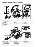
Page 4: ... tray 13 Bypass tray extension 14 Charger cleaner 15 USB 1 1 connector 16 Parallel connector 17 Document feeder tray when the SPF is installed 18 Original guides when the SPF is installed 19 Feeding roller cover when the SPF is installed 20 Right side cover when the SPF is installed 21 Exit area when the SPF is installed 22 Toner cartridge lock release lever 23 Toner cartridge 24 Roller rotating k...

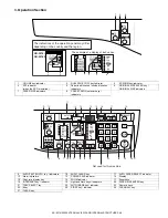
Page 5: ...5 Copy ratio display key 16 ZOOM indicator 17 Zoom keys 18 INTERRUPT key indicator 19 Light and Dark keys indicators 20 PAPER SIZE ENTER key 21 TRAY SELECT key 22 AUTO IMAGE key indicator 23 Numeric keys 24 key 25 START key indicator 26 CLEAR ALL key 27 CLEAR key The example of a display of inch series 200 50 141 95 77 64 129 121 11X17 8 X14 8 X11 8 X11 8 X5 EXTRA 8 X13 100 AR 5316 AR 5316X 4 5 Th...

Page 6: ... ORIGINAL SIZE ENTER key to select the paper size The indicator of the selected paper size lights up 4 Squeeze the lock lever of the front guide and slide the front guide to match the width of the paper and move the left guide to the appropriate slot as marked on the tray The front guide is a slide type guide Grasp the locking knob on the guide and slide the guide to the indicator line of the pape...

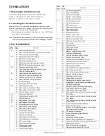
Page 7: ...splay 08 SPF counter display 09 Paper feed counter display 12 Drum counter display 13 CRUM type display 14 P ROM version display 22 15 Trouble memory display 17 Copy counter display 18 Printer counter display 21 Scanner counter display 22 SPF jam counter display 24 01 Jam total counter clear 02 Trouble memory clear 04 SPF counter clear 06 Paper feed counter clear 07 Drum counter clear 08 Copy coun...

Page 8: ...the simulation is terminated 02 SPF sensor status display In order to receive the sensor change notification the load must be decreased The sensor status ON OFF in the SPF can be checked with the following lamps When a sensor detects paper it turns on The open close detection sensor turns on when the machine is opened When the Interrupt key is pressed the machine goes to the sub code input standby...

Page 9: ...e machine goes into the sub code input standby mode When CA key is pressed the simulation is terminated 06 Transfer charger output Select an output mode with the Mode select key and press the START key The transfer charger output is delivered for 30 sec in the selected mode After 30 sec of transfer charger output the machine goes into the sub code entry standby mode When INTERRUPT key is pressed d...

Page 10: ...n the error display indicates the error position 12 Standby mode fusing fan RPM setting When this simulation is executed the currently set code number is displayed When MODE SELECT key is pressed the normal setting and the high fusing temperature setting are switched alternatively Enter the code number and press START key and the number is written into the EEPROM and the machine goes into the sub ...

Page 11: ...it is recommendable to use this simulation to set the scan position and execute the scan position automatic adjustment 64 01 Self print The optical system status is ignored and a self print is made Also when a print command is sent from the host printing is performed Operating procedure When this simulation is executed warm up is performed and the ready lamp is lighted However the scanner is inval...

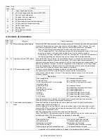
Page 12: ...1 4 When copying using the SPF during the period of time that the SPF indicator blinks after an original has been scanned about 5 seconds a subsequent original can be placed and automatically fed into the machine OFF 0 OFF 1 ON Auto power shut off setting 5 Use this setting to enable or disable auto power shut off ON 0 OFF 1 ON Auto paper select mode 2 8 This function automatically selects paper t...

Page 13: ...is sets the volume of beep signals short beep 1 short beep 2 long beep 3 OFF Base setting beep signal 28 Use this to sound a beep when a base setting is selected OFF 0 OFF 1 ON Number of copies limit 29 Use this setting to select 99 or 999 for the maximum number of copies 999 copies 1 99 copies 2 999 copies Use close paper size 30 When this function is enabled printing in printer mode will automat...

Page 14: ... X X Side Mylar Optical section Lamp unit Reflector O O O O Mirror O O O O No 2 3 mirror unit Mirror O O O O Pulley X X X X CCD peripheral Lens O O O O Glass Table glass O O O O White Plate O O O O Other Drive wire X X X X Rail X X X X Document cover O O O O Document size sensor O O O O LSU Dust proof glass O O O O Paper feed section Multi paper feed section Take up roller manual SPF O O O O Paper...

Page 15: ...heet so that the notch is on the outside Toner Life 16K Remaining quantity check 1 a Press and hold the density adjustment LIGHT key for more than 5 sec and the machine will enter the user program mode b Press and hold the key for more than 5 sec and the remaining quantity will be displayed on the copy quantity display in one of the following levels Remaining quantity display levels 100 75 50 25 1...

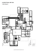
Page 16: ... S A G C M P X AD 16bit s CCD Driver CCFL Lamp Inverter HOME POSITION SENSOR CCD TCD1710 CRUM CPU CLK 19 6608MHz Software Reset SSCG PMD Driver MM_AI0 AI1 PH_A MM_BI0 BI1 PH_B OPU PWB LC7935AN 7seg LED LED 5V HC151 KEY 5V LVC1284 PDIUSBP11AD START KEY POWER SUPPLY POFF HL PR FW 3 3V 5VEN 5V 24V HVU TC GRID MC BIAS COIN VENDOR AUDITOR CV_COPY CV_COUNT CV_START CV_C A CV_DPX CV_SIZE0 1 2 3 PMCLK 207...

Page 17: ...OLING FUN I F FFC FFC FFC FFC FFC FFC Front Cover SW SRU CASETTE SWITCH SENSOR B3B PH K S WHITE B3B PH K R RED SUB D 25 FE4 32 S1505 BLACK B4B PH K S WHITE 08FE BT VK N WHITE B2P VH WHITE B3P VH WHITE B3B PH K S WHITE B20B PHDSS B WHITE B3B PH K BK BLACK B4B PH K S WHITE B2B XH A S WHITE B2B XH A BK BLACK B2B XH A R RED B4B PH K R RED B12B PHDSS B WHITE B26B PHDSS B WHITE 35FE BT VK N WHITE 13FE B...

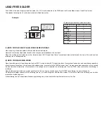
Page 18: ...tional one it is apt to keep the soldering iron in contact with the PWB for longer time This may cause land separation or may exceed the heat resistive temperature of components Use enough care to separate the soldering iron from the PWB when completion of soldering is confirmed Since lead free solder includes a greater quantity of tin the iron tip may corrode easily Turn ON OFF the soldering iron...

Page 19: ...lectronic mechanical photocopying recording or otherwise without prior written permission of the publisher Trademark acknowledgments Windows and Windows NT are trademarks of Microsoft Corporation in the U S A and other countries IBM and PC AT are trademarks of International Business Machines Corporation PCL is a trademark of Hewlett Packard Company Pentium is a registered trademark of Intel Corpor...

Reviews: