background image

b. SPF original off-center adjustment

Note:

Before performing this adjustment, be sure to check that the
paper off center is properly adjusted. 

1) Make a test chart for the center position adjustment and set it on

the SPF. 

<Adjustment specification>

Draw a line on a paper in the scanning direction. 

2) Make a normal copy from the manual paper feed tray, and com-

pare the copy and the original test chart.
If necessary, perform the following adjustment procedures. 

3) Execute SIM 50-16. 

4) After warmup, shading is performed and the current set value of

the off center adjustment at each paper feed port is displayed on
the display section in 2 digits. 

5) Enter the set value and press the start key. 

The set value is stored and a copy is made. 

<Adjustment specification>

Mode

Specification

SIM

Set value

Set range

Original
off center
mode
(SPF
mode)

Single:
Center 

±

 3.0mm

SIM

50-16

Add 1:
0.1mm shift to
R side
Reduce 1:
0.1mm shift to
L side

1 ~ 99

Duplex:
Center 

±

3.5mm

(8) OC (SPF) open/close detection position adjustment

1) Set A4 or 8 1/2" 

×

 11" paper on the OC table.

Check that the document size display on the operation panel indi-
cates the correct size of the set paper.

2) Close the OC (SPF) with a small clearance for insertion of your

hand left, and remove the paper from the OC table.
The document size display does not change from the display in 1).

3) Open the OC (SPF) slowly until the display on the operation panel

changes (all the document size display lamps are turned off), and
measure dimension A shown below under that state.

<Spec value>

OC (SPF) open/close position A: 207 

 302mm

4) If the OC (SPF) open/close position A is not 207 

 302mm, adjust

the open/close sensor mounting plate position as shown below.

(9) Original sensor adjustment (SIM 41-3)

<Other than AR-160>

1) Execute SIM 41-2.

2) Set A3 (11" x 17") paper on the OC table. 

3) Press the start key again. 

4) The sensor level of the original sensor is automatically checked

and the value with an original - 40 is made as the threshold value
for scanning. (Automatic setting)

5) Execute SIM 41-3.

6) The light reception level of the original sensor is displayed.

(The mode selection is made with the magnification ratio display
key.)

The first digit of the copy quantity display shows "A": Light recep-
tion level display

The first digit of the copy quantity display shows "b": Original
judgement level display

7) By changing the paper set on the original table, the original size

LED sensed by the sensor is lighted.

C. Image density adjustment

(1) Copy mode (SIM 46-1)

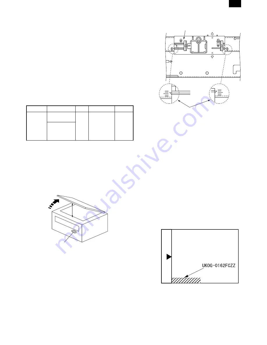
1) Set a test chart (UKOG-0162FCZZ) on the OC table as shown

below.

2) Put several sheets of A3 or 11" x 17" white paper on the test

chart. 

3) Execute SIM 46-1.

4) After warmup, shading is performed and the current set value of

the density level is displayed on the display section in 2 digits. 

For mode selection, use the density select key. 

5) Change the set value with the 10-key to adjust the copy image

density.

Open

A

Distance A = Table glass top - OC (SPF) knob 117"

Check the position where the display checked in 
procedure 1) is changed. 

(A)

(B)

Open/close sensor mounting plate

Factory setting : second from the top 

AR-205

AR-205 [6] ADJUSTMENT 05/24/1999

6 – 9

Summary of Contents for AR-160

Page 1: ...CATIONS 2 1 3 CONSUMABLE PARTS 3 1 4 EXTERNAL VIEWS AND INTERNAL STRUCTURE 4 1 5 UNPACKING AND INSTALLATION 5 1 6 ADJUSTMENTS 6 1 7 SIMULATIONS 7 1 8 USER PROGRAM 8 1 9 TROUBLE CODE LIST 9 1 10 MAINTENANCE 10 1 11 DISASSEMBLY AND ASSEMBLY 11 1 12 FLASH ROM VERSION UP PROCEDURE 12 1 13 ELECTRICAL SECTION 13 1 CONTENTS AR 205 SHARP CORPORATION This document has been published to be used for after sa...

Page 2: ...NING SOM ÖVERSKRIDER GRÄNSEN FÖR LASERKLASS 1 CAUTION VORSICHT ADVARSEL ADVERSEL VARNING VARO INVISIBLE LASER RADIATION WHEN OPEN AND INTERLOCKS DEFEATED AVOID EXPOSURE TO BEAM UNSICHTBARE LASERSTRAHLUNG WENN ABDECKUNG GEÖFFNET UND SICHERHEITSVERRIEGELUNG ÜBERERÜCKT NICHT DEM STRAHL AUSSETZEN USYNLIG LASERSTRÅLING VED ÅBNING NÅR SIKKERHEDSAFBRYDERE ER UDE AF FUNKTION UNDGA UDSAETTELSE FOR STRÅLING...

Page 3: ...ustment item list 6 1 2 Copier adjustment 6 1 7 SIMULATIONS 7 1 1 Entering the simulation mode 7 1 2 Cancelling the simulation mode 7 1 3 List of simulations 7 1 4 Contents of simulations 7 2 8 USER PROGRAM 8 1 1 List of user programs 8 1 2 Setting the user programs 8 1 9 TROUBLE CODE LIST 9 1 1 Trouble code list 9 1 2 Details of trouble codes 9 1 10 MAINTENANCE 10 1 1 Maintenance table 10 1 11 DI...

Page 4: ...etal piece drops into the machine turn off the power switch disconnect the power plug then remove the dropped thing 8 Do not use a wet hand to disconnect or insert the power plug and to operate or service the machine It may cause an electric shock B CAUTION 1 Avoid installation on an unstable surface or a slant surface Other wise it may drop from the surface resulting in an injury It is advisable ...

Page 5: ...0 161 Paper size Normal Enlargement 200 Reduction 50 AB system A3 9 9 9 B4 10 10 10 A4 16 16 14 A4R 12 12 12 B5 16 16 16 B5R 14 14 14 Inch system 11 17 9 9 9 8 5 14 10 10 10 8 5 13 10 10 10 8 5 11 16 16 14 8 5 11 R 12 12 12 8 5 5 5 16 16 16 b AR 200 205 Paper size Normal Enlargement 200 Reduction 50 AB system A3 11 11 11 B4 12 12 12 A4 20 20 20 A4R 14 14 14 B5 20 20 20 B5R 16 16 16 Inch system 11 ...

Page 6: ... detection by key input Paper size setting User setting by key input External dimensions W D H 590 471 88mm 590 471 173 5mm Weight About 5kg About 10kg Special paper Recycled paper Power Supplied from the machine G Job speed S S 1st step 100 document replacement rate AR 160 161 80 document replacement rate AR 200 205 Condition With SPF H Multi copy Max number of multi copy 99 sheets I Warmup time ...

Page 7: ...ly 2 in 1 4 in 1 Rotation copy Memory copy AR 200 205 and AR 161 for USA Canada Available Pre heat function Conditions set by the user program Auto power shut off function Conditions set by the user program Auto tray switching Message display FAX Printer extension User program Total counter Available Not available By the document size set key When an option is installed Q Other specifications Phot...

Page 8: ...um cartridge recycling Recommendation Note Maintenance parts other than mentioned above must be ordered through the parts department using the proper part number B Asia Southeast Asia NO Name Content Life Model name Package Remark 1 Developer cartridge Black Toner developer cartridge Toner 610g Developer 395g 1 15K AR 200TD 1 Life setting by A4 6 document Vinyl bag 1 2 Drum cartridge Drum cartridg...

Page 9: ...s of drum cartridge recycling Recommendation D Hong Kong China NO Name Content Life Model name Package Remark 1 Developer cartridge Black Toner developer cartridge Toner 610g Developer 395g 1 15K AR 200TD C 1 Life setting by A4 6 document Vinyl bag 1 2 Drum cartridge Drum cartridge 1 30K AR 200DR C 1 Vinyl bag 1 3 Toner kit Black Toner bottle Toner 610g 10 150K AR 200CT C 1 Life setting by A4 6 do...

Page 10: ... Ex option 2 Japan same pack 6 Ex same pack 7 Drum cartridge The label on the drum cartridge shows the date of production Division No Ex production 1 Option 2 Same pack 3 Temperature Humidity Temperature Humidity Humidity Temperature Use envi ronment conditions The end digit of production year January September October November December 1 9 0 X Y Indicates production in China Destination Serial nu...

Page 11: ...e developer on the MG roller and toner on the developing doctor completely with a vacuum cleaner or an air blower 7 Shake the developer bottle about 10 times and supply developer to the developing unit Turn the stirring roller to distribute developer evenly 8 Install the toner box 9 Shake the toner bottle about 20 times and install the toner supp ly hose to the toner bottle 10 Remove the toner cap...

Page 12: ...ching the DV blade When attaching the DV blade be careful not to scratch it and eliminate slack After attaching be careful not to scratch and damage the DV blade 17 Shake the developing unit 5 times left and right horizontally 18 Check the distribution state of developer on the MG roller Rotate the MG roller and visually check for no improper distribu tion of developer which may be caused by forei...

Page 13: ...ater If there is no damage execute the procedure of item 12 5 Remove the main charger Cleaning the screen grid and the sawteeth 6 Remove the cleaning blade Note Dispose the cleaning blade which was removed 7 Clean the cleaning section and the waste toner pipe to remove waste toner completely with a vacuum cleaner 8 Remove the felt and duplex tape completely Note Be careful not to scratch or bend t...

Page 14: ...Dia 2 13 Attach the detection gear Note The detection gear is not installed to the drum cartridge packed with the main body Add a new one 14 Attach the drum cover Note After attaching the drum cover do not make a copy 15 Mark the number of times of recycling on the side of the cover with white paint Max times of recycling 5 times AR 205 3 7 ...

Page 15: ... Paper tray 9 Side cover 10 Side cover handle 11 Bypass tray guides 12 Bypass tray 13 Bypass tray extension 14 Second cassette AR 200 205 only 2 Internal 1 Drum cartridge handle 2 Drum cartridge 3 TD cartridge handle 4 TD cartridge strap 5 TD cartridge 6 Roller rotating knob 7 Fusing unit release levers 8 Paper guide 9 3 11 12 13 14 2 3 4 5 6 7 8 10 1 2 3 4 5 6 7 8 AR 205 4 1 ...

Page 16: ...de is com pleted and that the fusing temperature is in ready state The combinations of the above display lamps are as follows ON OFF Lamp Immediately after power ON Ready Copying Pre heat lamp Blink Ready lamp Other lamps Lamp Energy saving mode Pre heating Energy saving mode Auto power shut off Resetting from energy saving mode Copy is started during resetting from energy saving mode Pre heat lam...

Page 17: ...ed clutch MPFC Drives the manual paper feed roller 11 Manual paper feed solenoid MPFS Manual paper feed solenoid 12 Manual paper transport clutch MPTC Drives the manual paper transport roller 13 Second tray transport clutch CPFC2 Drives the second tray transport roller 14 Second tray transport solenoid FSOL2 Second tray transport solenoid 15 First tray transport solenoid FSOL1 First tray transport...

Page 18: ...n 11 Shifter home position sensor SFTHP Shifter home position detection 12 Thermistor RTH Fusing section temperature detection 13 Thermostat Fusing section abnormally high temperature detection 14 1st tray detection switch 1st tray detection 15 Paper in PIN Paper transport detection 16 2nd tray detection switch 2nd tray detection 17 Manual sensor MPED Manual transport detection 18 Second cassette ...

Page 19: ...tage control 4 CCD sensor PWB Image scanning 5 Main PWB MCU Machine control Image process 6 Paper exit interface PWB Paepr exit finishing control 7 Tray interface PWB Paper tray control 8 Electronic sort function Operation panel input Display 9 Operation main PWB Operation panel input Display operation panel section control 1 2 3 4 9 8 6 5 7 AR 205 4 5 ...

Page 20: ...es 12 Transfer charger unit Transfer images on the drum onto paper 13 Duplex transport roller Transports paper for duplex only AR 205 14 Resist roller Takes synchronization between the paper lead edge and the image lead edge 15 Manual paper feed tray Manual paper feed tray 16 Manual paper feed roller Picks up paper in manual paper feed 17 No 2 3 mirror unit Reflects the images from the copy lamp u...

Page 21: ...er be sure to connect a grounding wire If no grounding wire is connected and a leakage occurs a fire or an electric shock may be result 2 Removal of protective material and fixing screw 1 Remove all tapes and protective material Remove all tapes then open the document cover and remove the protective material of sheet shape 2 Remove the fixing screw Use a coin to remove the fixing screw The fixing ...

Page 22: ...es When closing the side cover hold the knob When closing the covers be sure to close the front cover first then close the side cover If closed in a wrong sequence the covers may be broken 4 Removal and storage of fixing screw 1 Lift the knob and gently pull out the tray 2 Hold the paper pressure plate and turn the fixing screw in the arrow direction 3 Store the fixing pin and the fixing screw in ...

Page 23: ...per feed location indicator and the corresponding paper size which has been set indicator will blink All other indicators will go out For paper size setting ensure that the COPY mode has been selected However if printer or facsimile output is being per formed paper size setting cannot be made even in the COPY mode 9 Use the TRAY SELECT key to select the paper tray of which the paper size has been ...

Page 24: ...ping doctor fixing screw A 2 Insert a thickness gauge of 1 5mm to the three positions at 20mm and 130mm from the both ends of the developing doctor as shown 3 Push the developing doctor in the arrow direction and tighten the developing doctor fixing screw Perform the same procedure for the front and the rear frames 4 Check the clearance of the developing doctor If it is within the specified range ...

Page 25: ...t SIM 50 1 a OC image lead edge position adjustment Note In advance to this adjustment the sub scanning magnification ratio adjustment must be performed 1 Set a scale on the OC table as shown below 2 Make a copy 3 Check the copy output If necessary perform the following adjust ment procedures 4 Execute SIM 50 1 5 Set the OC lead edge position set value Exposure display AUTO ON to 99 The OC image s...

Page 26: ...st print surface lead edge position adjustment in advance and be sure to perform the second print surface lead edge position adjustment and then the lead edge void adjustment in this sequence Adjustment specification Adjustment mode SIM LED Set value Spec value Set range OC image lead edge position SIM 50 1 AUTO 99 R 0 127 Lead edge void 1 4mm Image loss 3mm or less 1 99 Main cassette lead edge vo...

Page 27: ...int surface auto duplex off center adjustment Ex posure display None Adjustment specification Mode SIM LED Set value Specifi cation Set range Paper off center SIM 50 10 Selected tray ON Add 1 0 127mm shift to R side Reduce 1 0 127mm shift to L side Single Center 2 0mm 1 99 Duplex Center 2 5mm Second print surface off center SIM 50 10 No display When SIM 48 01 AE is executed the document off center...

Page 28: ...with the positioning plate perform the adjustment of 4 4 Loosen the set screw of the scanner drive pulley which is not in contact with No 2 3 mirror base unit positioning plate 5 Without moving the scanner drive pulley shaft manually turn the scanner drive pulley until the positioning plate is brought into con tact with No 2 3 mirror base unit then fix the scanner drive pulley 6 Put No 2 3 mirror ...

Page 29: ...drive pulley shaft When La Lb Turn the mirror base drive pulley on the front frame side in the arrow direction A Do not move the mirror base drive pulley shaft 5 Tighten the mirror base drive pulley fixing screw Adjustment specification La Lb 6 Execute the main scanning direction FR distartion balance ad justment previously described in 2 again 4 Sub scanning direction scanning direction distortio...

Page 30: ...y scan the mirror base A and mirror base B fully and check that the mirror bases are not in contact with each other If the mirror base rail is moved extremely the mirror base may be in contact with the frame or the original glass Be careful to avoid this 5 Main scanning direction FR direction magnification ratio adjustment SIM 48 1 Note Before performing this adjustment be sure to check that the C...

Page 31: ...le as shown below and make a normal 100 copy to make a test chart Note Since the printed copy is used as a test chart put the scale in parallel with the edge lines 2 Set the test chart on the SPF and make a normal 100 copy 3 Compare the scale image and the actual image If necessary perform the following adjustment procedures 4 Execute SIM 48 5 5 After warmup shading is performed The auto density l...

Page 32: ... are turned off and measure dimension A shown below under that state Spec value OC SPF open close position A 207 302mm 4 If the OC SPF open close position A is not 207 302mm adjust the open close sensor mounting plate position as shown below 9 Original sensor adjustment SIM 41 3 Other than AR 160 1 Execute SIM 41 2 2 Set A3 11 x 17 paper on the OC table 3 Press the start key again 4 The sensor lev...

Page 33: ...level Sharp Gray Chart output Set value Set range Auto Auto 3 is slightly copied The greater the set value is the greater the density is The smaller the set value is the smaller the density is 1 99 Manual Manual 3 3 is slightly copied Photo Photo 3 3 is slightly copied Toner save Manual Photo 3 3 is slightly copied AR 205 6 10 ...

Page 34: ...play Japan only A 8 SPF counter display B 9 Paper feed counter display 12 Drum counter display 14 Copier ROM version display 15 Trouble memory display Main code Sub code Contents 22 16 Duplex print counter display C 17 Copy counter display 18 Printer counter display B 19 Electronic sort counter display B 20 FAX print counter display B 21 Scanner counter display 24 1 JAM memory JAM counter clear 2 ...

Page 35: ...Used to drive the SPF paper feed solenoid PSOL at the cycle of 500 msec ON and 500 msec OFF 20 times 9 RSPF reverse solenoid operation check Only when an option is installed Used to drive the RSPF reverse solenoid RSOL at the cycle of 500 msec ON and 500 msec OFF 20 times 10 RSPF paper exit gate solenoid operation check Only when an option is installed Used to drive the RSPF paper exit gate soleno...

Page 36: ...ted paper feed solenoid is driven at the cycle of 500 msec ON and 500 msec OFF 20 times 10 Main cassette semi circular roller drive Used to rotate the semi circular roller of the main cassette one turn to face it downward Display Lighting at sensor ON Shifter HP sensor Machine position JAM LED Job separator HP sensor SPF JAM LED Paper exit full sensor Second cassette position JAM LED Key operation...

Page 37: ...ion check Only AR 205 Used to rotate the duplex motor forward for 30 sec 2 Duplex motor reverse rotation operation check Only AR 205 Used to rotate the duplex motor reversely for 30 sec 4 Duplex motor rotation speed adjustment Only AR 205 The currently set duplex motor rotation speed set value is displayed When the set value is entered and the start key is pressed the set value is stored 6 1 13 5 ...

Page 38: ...eveloping unit counter value 1 7 Developing preset counter value display Japan only Used to display the current mini maintenance preset value set with SIM 21 2 1 8 SPF counter display Only when an option is installed Used to display the current SPF counter value 1 9 Paper feed counter display Used to display the current paper feed counter value for each paper feed port 1 12 Drum counter display Us...

Page 39: ...ion is installed Used to clear the SPF counter 2 5 Duplex counter clear Only AR 205 Used to clear the duplex counter 2 6 Paper feed counter clear Used to clear the paper feed counter 2 7 Drum counter clear Used to clear the drum counter 2 8 Copy counter clear Used to clear the copy counter 2 9 Printer counter clear Only when an option is installed Used to clear the printer counter 2 10 Electronic ...

Page 40: ...an option installed When A is displayed Shifter Paper empty LED Job separator JAM LED SPF SPF select LED RSPF SPF JAM LED Duplex mode Main cassette select LED Simplex mode Multi manual paper feed select LED When b is displayed Cassette 2nd step No 2 cassette select LED Cassette 3rd step No 3 cassette select LED Cassette 4th step No 4 cassette select LED Memory installed Paper empty LED FAX JAM LED...

Page 41: ...value 0 0 1 42 Transfer timing adjustment After completion of warm up shading is performed and the currently set transfer timing adjustment value is displayed 5 1 3 5 7 9 50 Black white reversion function setup The current setup of black white reversion is displayed with the following numbers After entering the set value press the start key to store the set value 0 0 1 Key operation Display 0 AL 1...

Page 42: ... is 155 190 C Use the magnification ratio key to adjust the value by 5 C 180 155 190 46 1 Copy density level adjustment After completion of warmup shading is performed and the currently set copy density level is displayed For the adjustment procedure refer to the previous descriptions 48 1 99 2 Display after clearing each counter 000 0 75 sec Blank 0 35 sec 000 0 75 sec Blank 1 0 sec Repetition Ke...

Page 43: ...d After completion of warmup shading is performed and the currently set OC mode sub scanning direction magnification ratio adjustment in FAX is performed For the adjustment procedure refer to the previous descriptions 50 1 99 7 SPF mode sub scanning direction magnification ratio adjustment in FAX Only when an option is installed After completion of warmup shading is performed and the currently set...

Page 44: ... when an option is installed After completion of warmup shading is performed and currently set value is displayed 58 1 99 Key operation Display Adjustment mode select Exposure mode select key Set value Copy quantity keys Auto Copy lead edge adjustment Manual SPF lead edge adjustment Not used Photo Main cassette lead edge void adjustment Auto Manual Left edge void adjustment Auto Photo Rear edge vo...

Page 45: ... pixel at the center at that time is displayed 64 1 Self print mode Disregards the optical system and performs self printing in 1 by 2mode 67 14 Printer Flash ROM Data Download Only when an option is installed The machine enters the version up mode of the printer PWB flash ROM For details refer to the AR PB8 Service Manual Key operation Display Adjustment mode select Exposure mode select key Auto ...

Page 46: ... 19 Offset of paper output tray Enables or disables the offset function of the paper output tray The offset function can be specified respectively for the upper and lower areas separated by an optional job separator tray kit Program No Program name Description 20 Image rotation in duplex copying Enables or disables image rotation 180 of the front side in one sided to two sided copying or two sided...

Page 47: ...ight side of the copy quantity display 1 Select the desired setting using the numeric keys 0 OFF 1 ON 2 Press the START key The setting will be stored 3 To continue with other user programs press the key and enter another program number To exit the user program mode press the light key B Program No 11 Account number entry Program No 11 is used to register accounts When program No 11 is entered 1 E...

Page 48: ...ample 1 234 copies The upper limit for the number of copies is 49 999 If the num ber of copies made reaches 50 000 the number will be reset to 0 and counting will start again from 0 3 Repeat steps 1 and 2 for other account numbers 4 To continue with other user programs press the key and select another program number To exit the user program mode press the light key F Program No 15 Resetting accoun...

Page 49: ...ro cross pulse FW trouble U2 04 EEPROM serial communication error 11 Counter check sum error 12 Adjustment value check sum error EEPROM U3 29 Mirror base home position error U9 00 Operation control PWB communication trouble 80 Operation control PWB communication trouble Protocol 81 Operation control PWB communication trouble Parity 82 Operation control PWB communication trouble Overrun 84 Operatio...

Page 50: ...ripheral circuit error Check and remedy Replace the E Sort PWB Replace the SIMM Check grounding of the machine 17 Content E Sort PWB image rotating RAM error Detail E Sort PWB image rotating RAM abnormality Main code Sub code Detail of trouble E11 17 Cause A image rotating RAM abnormality is detected in the E Sort PWB Control circuit hung up due to noises Image rotating RAM peripheral circuit erro...

Page 51: ...SU Laser power voltage failure Laser emitting diode abnormality MCU PWB abnormality Main code Sub code Detail of trouble E7 03 Check and remedy Improper connection of the LSU connector Check the polygon motor operation with SIM 25 10 Check printing with SIM64 1 Check laser emission of laser emitting diode Check the LSU unit Check the MCU PWB 04 Content CCD white level trouble Detail CCD white refe...

Page 52: ...fect Scanner wire disconnection Check and remedy Check the scanning operation with SIM 1 1 Main code Sub code Detail of trouble L3 00 Content Mirror base return trouble Detail The mirror home position MHPS does not turn on though the mirror base returning is completed during mirror initial operation after turning on the power The mirror home position does not turn on when the mirror is returned to...

Page 53: ...ection Operation control PWB MCU PWB harness failure Main code Sub code Detail of trouble U9 00 Check and remedy Check the connectors and harness of the operation control PWB and the MCU PWB Check grounding of the machine Check the ROM of the operation control PWB 80 Content Operation control PWB communication trouble Protocol Detail Communication trouble between MCU and the operation control PWB ...

Page 54: ... Check connector harness between FAX control PWB and MCU PWB Check grounding of the machine Check FAX control PWB ROM Main code Sub code Detail of trouble F6 81 Content FAX control PWB communication trouble Parity Detail Communication trouble between MCU and FAX control PWB Parity error Cause Bad connection of FAX control PWB connector Defective harness between FAX control PWB and MCU PWB Motherbo...

Page 55: ...ntent Printer PWB trouble Detail Communication trouble between MCU and printer PWB Main code Sub code Detail of trouble F9 10 Cause Bad connection of printer PWB connector Defective harness between printer PWB and MCU PWB Motherboard connector pin breakage Printer PWB ROM error data error Check and remedy Check connector harness of printer PWB and MCU PWB Check grounding of the machine Check print...

Page 56: ...plate Other Drive wire Rail Document cover Document size sensor LSU Dust proof glass Paper feed section Multi paper feed section Takeup roller Paper feed roller Spring clutch Cassette section Paper feed roller Spring clutch Paper transport section PS roller Transport paper exit rollers Spring clutch Fusing section Upper heat roller Pressure roller Pressure roller bearing Upper separation pawl Lowe...

Page 57: ...sport section 12 7 9 Manual multi paper feed section 12 8 10 Power section 12 10 11 Developing section 12 11 12 Process section 12 12 1 High voltage section Duplex transport section No Content A Transfer charger unit B Charger wire C Duplex transport section Only AR 205 A Transfer charger unit B Charger wire Installation The spring tip must be between two reference ribs The charger wire must be fr...

Page 58: ...it Disassembly Be sure to put No 2 3 mirror unit to the positioning plate A Assembly Put the notched surface of wire holder 3 downward tighten temporarily and install Adjustment Main scanning direction distortion balance adjustment C Copy lamp D Lens unit 1 1 2 3 3 4 2 3 2 3 1 A A 4 4 5 6 4 5 3 1 1 2 AR 205 11 2 ...

Page 59: ...ouch the other screws than the unit attachment screw The lens unit is supplied only in a whole unit 3 Fusing section No Contents A Fusing unit B Thermostat C Thermistor D Heater lamp E Upper heat roller F Separation pawl G Lower heat roller A Fusing unit removal 2 3 1 1 B Thermostat C Thermistor Installation Check that the thermistor is in contact with the upper heat roller D Heater lamp Assembly ...

Page 60: ...remove The heater lamp is fixed on the fusing cover with a screw Slide the fusing cover to the front and remove the screw then remove the heater lamp Assembly Put the fusing harness A on the heater lamp B as shown in the figure and fix them together Place the fusing harness inside the rib C E Upper heat roller F Separation pawl 3 4 3 B A 6 5 8 9 7 8 1 0 A B C 2 1 4 3 3 2 1 2 2 1 1 3 3 AR 205 11 4 ...

Page 61: ... guide fixing plate 2 is in contact with the frame bottom section A under fusing 4 Paper exit section No Content A Front cabinet unit Right cabinet unit B Ozone filter C Paper exit unit D Transport roller E Paper exit roller A Front cabinet unit right cabinet disassembly B Ozone filter 3 2 1 1 6 6 5 4 5 5 1 4 1 2 3 2 A AR 205 11 5 ...

Page 62: ...Assembly Insert the spring pin so that the waveform A of the spring pin faces in the longitudinal direction of the paper exit drive gear long hole B Be sure to insert two ribs C into the groove D 1 2 1 3 4 6 7 5 5 1 3 2 2 1 2 3 3 7 6 8 6 8 1 0 9 9 AR 205 11 6 ...

Page 63: ... the EEPROM of the MCU PWB to be replaced 6 Optical frame unit No Content A Optical frame unit A Optical frame unit Installation Install the optical unit in the sequence shown above 7 LSU No Content A LSU unit A LSU unit 4 4 5 B A D C C 8 6 6 7 7 1 1 2 1 1 1 1 2 1 2 3 1 2 1 1 3 4 AR 205 11 7 ...

Page 64: ...terface frame unit B Drive unit C Solenoid paper feed solenoid resist roller solenoid D Resist roller clutch Resist roller E Paper feed clutch Paper feed roller Semi circular roller A Intermittent frame unit Assembly Do not miss the door lock pawl B Drive unit Assembly Move down the clutch pawl as shown below and avoid the clutch and install 6 5 5 1 1 2 2 4 3 1 2 AR 205 11 8 ...

Page 65: ...er feed roller Semi circular roller 9 Manual multi paper feed section No Content A Manual multi paper feed section B Manual transport clutch C Manual paper feed clutch D Manual transport roller Manual paper feed roller E Multi feed solenoid A Manual multi paper feed 1 2 2 3 1 4 3 2 3 3 4 1 3 2 2 1 2 3 A AR 205 11 9 ...

Page 66: ... arm 1 then remove it Assembly Install so that the boss section of the fulcrum arm 2 comes between ribs Disassembly Set up the cam transmission arm 2 and remove it Assembly Install so that the cam transmission arm 2 is under the roller arm A 5 1 1 2 3 4 1 2 4 3 A 7 5 6 8 AR 205 11 10 ...

Page 67: ...reful of the installing direction of the manual transport roller 4 E Multi feed solenoid Assembly Install so that the latches A and B move smoothly 10 Power section No Content A Power unit A Power unit L C K T O K O 2 3 1 4 5 2 1 2 A B 3 4 5 3 3 4 2 1 1 1 1 AR 205 11 11 ...

Page 68: ... Developing box C Developing doctor D MG roller A Waste toner box B Developing box C Developing doctor Adjustment Developing doctor gap adjustment D MG roller Adjustment MG roller main pole position adjustment 1 1 2 1 2 1 2 1 1 2 1 3 4 5 6 3 AR 205 11 12 ...

Page 69: ... MC holder unit C Cleaning blade A Drum unit Assembly When installing the drum cover 1 be sure to engage the transport screw gear A rib and the detection gear B B MC holder unit C Cleaning blade 1 L O C K A B L O C K 2 3 2 1 1 2 1 1 AR 205 11 13 ...

Page 70: ...ap at the rear of the machine 4 Connect the serial connector 5 Turn on the power of the machine The machine enters the download mode All LED lamps are turned off The machine accepts no key operations 6 Execute mainte Vxxx exe on the PC Use mainte_vxxx exe ver 1 04 or later 7 Communication port communication speed setting Select Comport in the option menu and select the most suitable item with cons...

Page 71: ... Menu ITEM Configuration Page ENTER The test page prints 2 Connect the PC and the copier with the parallel cable 3 Turn on the power 4 Execute SIM 67 14 Erase Flash Data is displayed on the LCD 5 Press the ENTER key on the copier s operation panel Now Erasing is displayed on the LCD 6 After deletion of data Please Send Data is displayed on the LCD and the machine enters the ready state for data in...

Page 72: ... 13 ELECTRICAL SECTION 1 BLOCK DIAGRAM AR 205 13 1 ...

Page 73: ...2 ACTUAL WIRING DIAGRAM ACTUAL WIRING DIAGRAM 1 3 13 2 13 3 AR 205 AR 205 ...

Page 74: ...ACTUAL WIRING DIAGRAM 2 3 13 4 13 5 AR 205 AR 205 ...

Page 75: ...ACTUAL WIRING DIAGRAM 3 3 13 6 13 7 AR 205 AR 205 ...

Page 76: ... a retrieval system or transmitted in any form or by any means electronic mechanical photocopying recording or otherwise without prior written permission of the publisher SHARP CORPORATION Printing Reprographic Systems Group Quality Reliability Control Center Yamatokoriyama Nara 639 1186 Japan 1999 June Printed in Japan N AR 205 ...

Reviews: