3
4
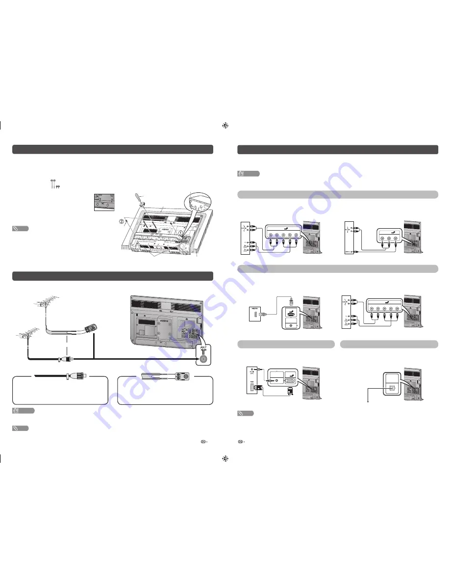
Attaching the stand
• Before attaching (or detaching) the stand, unplug the AC cord from the AC outlet.
• Before performing work spread cushioning over the base area to lay the TV on. This will prevent it from
being damaged.
1
Confi rm the screws supplied with the TV.
DIGITAL
AUDIO
OUTPUT
INPUT 2
INPUT 1
AUDIO IN
(R/L)
INPUT 6
PC
ANTENNA
1
3
3
6
6
ANT
Soft cushion
Screw driver
Screw
Stand base
guide pins
Guide pin holes
Table edge
Screws (
m
4)
(used in step 3)
2
Insert the stand base guide pins to the
stand holes on the rear of the TV. (
1
)
• Make sure the symbol on the stand base is
parallel with the triangle symbol located at
the back of the TV.
3
Insert and tighten the 4 screws into the 4 holes
on the rear of the stand base. (
2
)
NOTE
• To detach the stand, perform the steps in reverse order.
• The TV position setting is set to 7˚ backward after attaching
the stand.
• Do not remove the plastic wrap before attaching the stand
base to protect it from scratches.
• The bottom area of the set (curvy area) must be beyond the
table’s edge to prevent the TV from damage.
Antenna connection
Connecting the antenna cable
To enjoy a clearer picture, use an outdoor antenna.
ANT
DIGITAL
AUDIO
OUTPUT
INPUT 2
INPUT 1
AUDIO IN
(R/L)
INPUT 6
PC
ANTENNA
3
3
300-ohm twin-
lead fl at feeder
(not supplied)
VHF/UHF
antenna
VHF/UHF
antenna
or
75-ohm coaxial
cable (round cable)
(not supplied)
Standard DIN45325 plug (IEC 169-2)
75-ohm
impedance
converter
(not supplied)
To antenna terminal
If your outdoor antenna uses a 75-ohm coaxial
cable with a standard DIN45325 plug (IEC 169-
2), plug it into the antenna jack at the rear of the
set.
If your outdoor antenna uses a 300-ohm twin-
lead fl at feeder, connect a 300-ohm to 75-ohm
impedance converter and plug it into the antenna
jack at the rear of the set.
CAUTION
•
TO PREVENT RISK OF ELECTRIC SHOCK, DO NOT TOUCH UN-INSULATED PARTS OF ANY CABLES WITH
THE AC CORD CONNECTED.
NOTE
• Place the TV close to the AC outlet, and keep the power plug within reach.
Connecting external devices
You can connect many types of external equipment to your TV, like a VCR, game console, camcorder, DVD
player, Digital TV STB (Set Top Box) and PC. To view external source images, select the input source from
INPUT
on the remote control unit or
INPUT
on the TV.
CAUTION
• To protect all equipment, always turn off the TV before connecting to a VCR, game console, camcorder, DVD player, Digital
TV STB (Set Top Box), PC or other external equipment.
• Refer to the relevant operation manual (VCR, DVD player, etc.) carefully before making connections.
Connecting a VCR, game console or camcorder
A VCR, game console, camcorder and some other audiovisual equipment can be conveniently connected
using the INPUT 4 or INPUT 5 terminals.
When using component cable
(commercially available)
When using composite cable
(commercially available)
ANT
DIGITAL
AUDIO
OUTPUT
INPUT 2
INPUT 1
AUDIO IN
(R/L)
INPUT 6
PC
ANTENNA
3
3
4
INPUT 4
R-AUDIO-L
Y
P
B
(C
B
) P
R
(C
R
)
VCR/Game console/Camcorder
ANT
DIGITAL
AUDIO
OUTPUT
INPUT 2
INPUT 1
AUDIO IN
(R/L)
INPUT 6
PC
ANTENNA
3
3
INPUT 5
R-AUDIO-L
VIDEO
5
VCR/Game console/Camcorder
Connecting a DVD player/Digital TV STB (Set Top Box)
You can use the INPUT 1/INPUT 2/INPUT 3 (HDMI), INPUT 4 terminals when connecting to a DVD player/
Digital TV STB (Set Top Box) and other audiovisual equipment.
When using HDMI-certifi ed cable
(commercially available)
When using component cable
(commercially available)
ANT
DIGITAL
AUDIO
OUTPUT
INPUT 2
INPUT 1
AUDIO IN
(R/L)
INPUT 6
PC
ANTENNA
3
3
INPUT 1
AUDIO IN
(R/L)
1
DVD player/Digital TV
STB (Set Top Box)
ANT
DIGITAL
AUDIO
OUTPUT
INPUT 2
INPUT 1
AUDIO IN
(R/L)
INPUT 6
PC
ANTENNA
3
3
4
INPUT 4
R-AUDIO-L
Y
P
B
(C
B
) P
R
(C
R
)
DVD player/Digital TV STB (Set Top Box)
Connecting a PC
Using Digital Audio Output
You can use the INPUT 6 PC terminals when
connecting to a PC of ANALOGUE RGB terminal.
ANT
DIGITAL
AUDIO
OUTPUT
INPUT 2
INPUT 1
AUDIO IN
(R/L)
INPUT 6
PC
ANTENNA
3
3
AUDIO IN
(R/L)
INPUT 6
PC
ANALOGUE
6
PC
ANALOGUE RGB
It is possible to output audio through the DIGITAL
AUDIO OUTPUT terminal. PCM audio outputs from
the terminal.
ANT
DIGITAL
AUDIO
OUTPUT
INPUT 2
INPUT 1
AUDIO IN
(R/L)
INPUT 6
PC
ANTENNA
3
3
DIGITAL
AUDIO
OUTPUT
Optical fi bre cable
(commercially
available)
To optical digital input of external audio devices
NOTE
• The DIGITAL AUDIO OUTPUT terminal usually outputs the same audio from the speakers. (The audio of the content you are
viewing is output from the terminal.)
• The DIGITAL AUDIO OUTPUT terminal does not output some signals, depending on devices and software.
• The DIGITAL AUDIO OUTPUT terminal does not output any signal during HDMI digital input.
LC-32LE550M _EN767.indd 2
LC-32LE550M _EN767.indd 2
12/5/2012 10:12:56 AM
12/5/2012 10:12:56 AM