LC-80LE632U
4 – 7
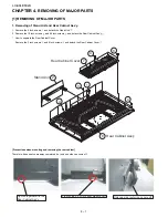
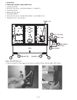
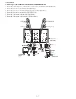
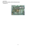
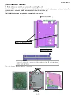
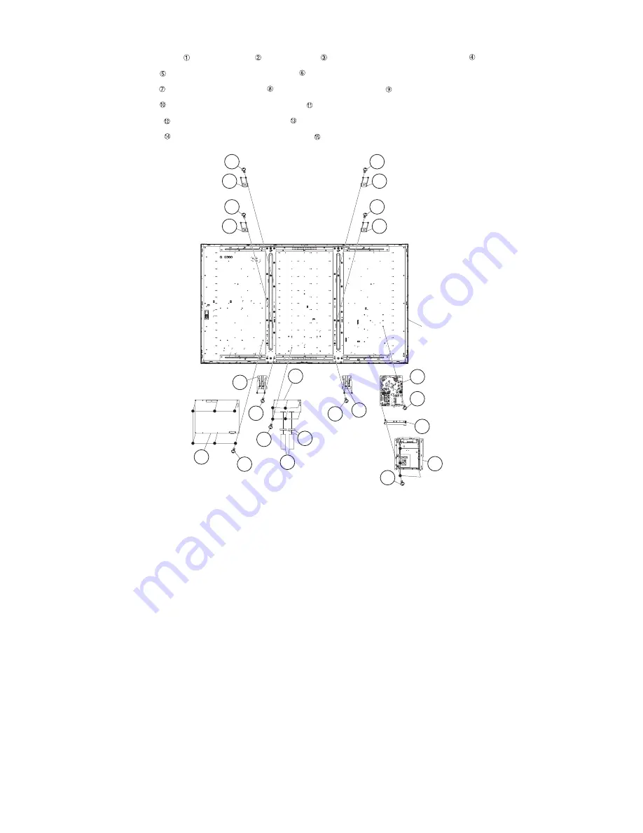
4. Removing of LCD CONTROL Unit, MAIN Unit, POWER/DRIVE Unit.
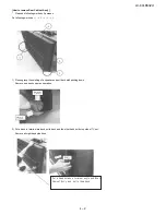
1. Remove the 2 Connecting Cords , 2 Ferrite Cores , 6 lock screws and detach the LCD CONTROL Unit .
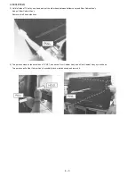
2. Remove the 5 lock screws and detach the Shield (MAIN Unit) .
3. Remove the 3 lock screws and detach the MAIN Unit and Terminal Angle (Bottom) .
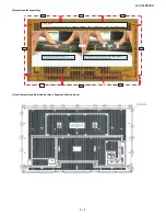
4. Remove the 6 lock screws and detach the POWER/DRIVE Unit .
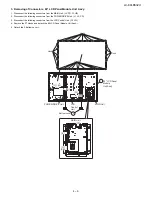
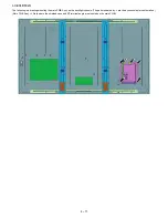
5. Remove the 12 lock screws and detach the 2 Stand Angles .
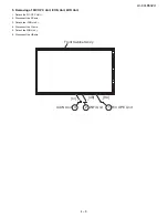
6. Remove the 16 lock screws and detach the 4 VESA Angle Ass’ys .
80" LCD Panel
Module Unit
11
10
1 FFC
2 Ferrite
Core
LCD
Control
Unit
12
3
13
12
POWER/
DRIVE
Unit
Stand Angle
13
Stand
Angle
8
5
4
Terminal
Angle
(Bottoom)
7
Shield
(MAIN Unit)
6
MAIN Unit
9
14
15 VESA Angle Ass'y
14
15 VESA Angle Ass'y
14
15
VESA Angle
Ass'y
14
15
VESA Angle
Ass'y
Summary of Contents for AQUOS LC-80LE632U
Page 40: ...LC 80LE632U 6 2 M E M O ...
Page 49: ...LC 80LE632U ...


