LC-40/46LE814/824E/RU (1st Edition)
12
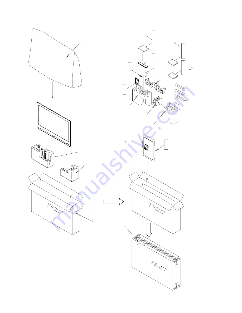
[8] PACKING PARTS (NOT REPLACEMENT ITEM)(LC-40LE814/824E/RU)
S2
S6
S1
S10
S9
S4
S8
for Europe
for Russia
S7
S3
S5
X8
X18
X3
X2
X11
X15
X10
X14
X9
X12
X13
X16
X4
X17
X1
X5
X6X7
Page 1: ...ABLE 1 TROUBLESHOOTING TABLE 5 1 2 LED flashing specification at the time of the error 5 14 CHAPTER 6 MAJOR IC INFORMATIONS 1 MAJOR IC INFORMATIONS 6 1 CHAPTER 7 OVERALL WIRING BLOCK DIAGRAM 1 OVERALL WIRING DIAGRAM LC 40LE814E RU 7 1 2 OVERALL WIRING DIAGRAM LC 46LE814E RU 7 2 3 OVERALL WIRING DIAGRAM LC 40LE824E RU 7 3 4 OVERALL WIRING DIAGRAM LC 46LE824E RU 7 4 5 SYSTEM BLOCK DIAGRAM LC 40LE814...
Page 2: ...CONTROL Unit RUNTK4512TPZC No change LCD PANEL MODULE N 40 LCD Panel Module Unit R1LK400D3LWF2Y No change CABINET PARTS Please refer to a Parts Guide SUPPLIED ACCESSORIES Please refer to a Parts Guide PACKING PARTS NOT REPLACEMENT ITEM Please refer to a Parts Guide SERVICE JIGS USE FOR SERVICING Please refer to a Parts Guide Ref No Description LC 46LE810E No S30E940LE810E LC 46LE814E RU No S90K840...
Page 3: ... SERVICE JIGS USE FOR SERVICING Please refer to a Parts Guide Ref No Description LC 46LE820E No S30F240LE820E LC 46LE824E RU No S90K840LE814E Interchangeability Note PRINTED WIRING BOARD ASSEMBLIES N MAIN Unit DKEYDF455FM01 DKEYDF455FM12 Changed N ICON Unit DUNTKF493FM03 No change N LOGO Unit DUNTKF493FM04 No change N R C LED Unit DUNTKF494FM02 No change N POWER LED CONTROL Unit RUNTKA686WJQZ No c...
Page 4: ...oltage drop across the resistor All checks must be repeated with the AC cord plug connection reversed If necessary a nonpolarized adaptor plug must be used only for the purpose of completing these checks Any reading of 1 05 V peak this corresponds to 0 7 mA peak AC or more is excessive and indicates a potential shock hazard which must be corrected before returning the monitor to the owner SAFETY N...
Page 5: ...nventional lead solder by 40 C and as it has poor solder wettability you may be apt to keep the soldering bit in contact with the PWB for extended period of time However Since the land may be peeled off or the maximum heat resistance temperature of parts may be exceeded remove the bit from the PWB as soon as you confirm the steady soldering condition Lead free solder contains more tin and the end ...
Page 6: ...LC 40 46LE814 824E RU 1st Edition v End of life disposal End of life disposal ...
Page 7: ...OWER LED CONTROL Unit LC 46LE814E RU LC 46LE824E RU N RUNTKA692WJQZ TOUCH SENSOR Unit LC 40LE814E RU LC 46LE814E RU N RUNTKA761WJQZ TOUCH SENSOR Unit LC 40LE824E RU LC 46LE824E RU 2 N RUNTK4512TPZC LCD CONTROL Unit Ref No Parts Code Description N R1LK400D3LWF2Y 40 LCD Panel Module Unit LC 40LE814E RU N R1LK460D3LWG2Y 46 LCD Panel Module Unit LC 46LE814E RU N R1LK400D3LWF0Y 40 LCD Panel Module Unit...
Page 8: ...X E 4 I M D H B S U B S U ETHERNET 10 100 HDMI 2 EXT 3 AUDIO L R 1 DIGITAL AUDIO OUTPUT C I Common Interface OUTPUT Headphones k e e r G n a m r e G h c n e r F h s i n n i F n a i n o t s E h s i l g n E h c t u D h s i n a D h c e z C e g a u g n a l D S O Hungarian Italian Latvian Lithuanian Norwegian Polish Portuguese Russian Slovak Slovene Spanish Swedish Turkish Ukrainian Power requirement A...
Page 9: ...VIDEO AUDIO L R terminal 10 EXT 3 ANALOGUE RGB PC COMPONENT terminal 11 HDMI 2 EXT 3 AUDIO L R jack 12 HDMI 1 HDMI ARC terminal 13 HDMI 2 HDMI terminal 14 HDMI 3 HDMI terminal 15 HDMI 4 HDMI terminal 16 C I COMMON INTERFACE slot 17 MAIN POWER switch WARNING Excessive sound pressure from earphones and headphones can cause hearing loss Do not set the volume at a high level Hearing experts advise aga...
Page 10: ...iplex mode Wide mode Select a wide mode 6 7 5 4 3 8 9 10 12 13 14 11 2 1 16 15 LE824E 17 18 19 20 21 22 23 24 4 3 LE814E 9 Mute TV sound on off 10 Volume Increase decrease TV volume 11 Menu screen on off 12 None OK MENU This key does not work on this model 13 Cursor Select a desired item Execute a command ATV DTV SAT Display CH list when no other Menu screen is running 14 ATV DTV SAT Exit the Menu...
Page 11: ... four holes on the rear of the TV 5 Attaching the stand cover Slide the stand cover into the two catches on the stand base Insert and tighten a short screw into the hole on the centre of the stand cover NOTE To detach the stand unit perform the steps in reverse order A screwdriver is not supplied with this product The stand base is made of glass Therefore be careful not to drop the stand base or a...
Page 12: ... 300 0 400 0 400 0 503 2 503 2 577 6 577 6 1023 4 890 6 1023 4 890 6 LC 46LE824E LC 46LE824RU LC 40LE824E LC 40LE824RU 1125 0 992 0 1125 0 992 0 540 0 540 0 450 0 450 0 784 0 706 0 784 0 706 0 400 0 300 0 400 0 300 0 733 0 658 0 733 0 658 0 404 0 404 0 444 0 444 0 48 0 48 0 51 0 51 0 132 0 132 0 211 0 211 0 39 5 39 5 124 0 124 0 157 1 157 1 275 0 275 0 340 0 340 0 300 0 300 0 400 0 400 0 500 4 500...
Page 13: ...to select the item HDMI EDID WRITE on the page 5 21 2 After replacing the LCD panel or LCD control MAIN UNIT check MODEL NAME in the following procedure 1 Enter the process adjustment mode in TV 2 Use the cursor keys and CH keys of R C to select the item MODEL NAME on the page 21 21 3 Verify that the Model name is displayed 4 If the Model name doesn t match select the values of the Model name with...
Page 14: ...le The letter K appears on the screen This state is in Inspection mode 2 Next hold down the VOL and CH keys on the set at once Multiple lines of blue characters appearing on the screen indicate that the set is now in the adjustment Process mode If you fail to enter the adjustment process mode the display is the same as normal startup retry the procedure 3 To exit the adjustment process mode after ...
Page 15: ...6 Item name Max 30 char 7 Parameter Max 60 char 1 Present page number of total pages 4 Inducing display 3 Present colour system 2 Input that has been selected now 5 Inch setting and Model name display 6 Item name 7 Parameter 1 00 E 2009 xxxxxxx xxxxxxx xxxxxxxx xxxx xxxxxxx xxxxx YES xxxxxxx xxxxxxx xxxxxxx 0 1 xxxxxx 2 xxxxxx 3 xxxxxx 4 xxxxxx 0 0 0 0 0 1 21 INPUT1 AUTO EURO xxxxx MAIN Version BO...
Page 16: ...ating hours reset 8 LAMP ERROR RESET OFF Lamp error reset 9 ADJ PARAM SET Enter ADJ PARAM SET 10 VIC XPOS 0 X coordinate setting for VIC READ 11 VIC YPOS 0 Y coordinate setting for VIC READ 12 VIC SIGNAL TYPE MAIN Signal type setting for VIC READ 13 VIC READ OFF Picture level acquisition function Level appears in green on the upper right 3 21 1 TUNER ADJ Enter TUNER auto adjustment execution 2 PAL...
Page 17: ...OG video level adjustment 2 R OFFSET 64 R CUTOFF adjustment value 3 G OFFSET 64 G CUTOFF adjustment value 4 B OFFSET 64 B CUTOFF adjustment value 5 R GAIN 44 R DRIVE adjustment value 6 G GAIN 44 G DRIVE adjustment value 7 B GAIN 44 B DRIVE adjustment value 9 21 1 SCART RGB ADJ Enter SCART RGB level adjustment 2 SCART R CUTOFF 64 SCART R CUTOFF adjustment value 3 SCART G CUTOFF 64 SCART G CUTOFF ad...
Page 18: ... KEY SENSITIVITY 0 7 VOL DOWN KEY SENSITIVITY 0 17 21 1 KEY STRENGTH GET MODE Enter 2 POWER KEY STRENGTH 3 MENU KEY STRENGTH 4 INPUT KEY STRENGTH 5 CH UP KEY STRENGTH 6 CH DOWN KEY STRENGTH 7 VOL UP KEY STRENGTH 8 VOL DOWN KEY STRENGTH 18 21 1 READ WRITE READ Read Write 2 SLAVE ADDRESS SLAVE0 Slave address 3 REGISTER ADDRESS 0x 0 Register address 0x 0 4 WRITE DATA 0x 0 Writing data 0x 0 5 READ DAT...
Page 19: ...et of monitor error cause 4 MODEL NAME LE824 MODEL NAME 5 PANEL SIZE 40 Panel size setting 6 SHORT CHECK MODE Enter Check LED Back light 7 SHORT CHECK CURRENT 60 8 CURRENT SW LOW 9 PRODUCT EEP ADR 0x 0 Don t touch when serving for producer of factory 10 PRODUCT EEP DATA 0x 0 Don t touch when serving for producer of factory 11 PRODUCT FACTORY 1 Don t touch when serving for producer of factory T Tim...
Page 20: ...mode Please execute Lamp Error detection off mode While holding down the VOL and CH keys on the set at once touch the power supply key on the set After a central icon flash off separate the fingers from key on the set Touch the power supply key on the set again so the power will boot up Then you can check the operation to see if the lamp and lamp circuit are in trouble If you fail boot up retry th...
Page 21: ...etely input the Pass Word is judged d Check the Pass Word by inputting three digits If the Pass Word 0 2 7 it shifts to the PUBLIC Mode setting screen In another case the screen is erased and it operates in the ordinary mode 2 Exiting the Public Mode Setting screen There are two following ways to exit the Public Mode setting screen 1 Turn off the power 2 Select Execution in the PUBLIC_Mode to exec...
Page 22: ... VARIABLE VOLUME FIXED LEVEL 20 RC BUTTON RESPOND PANEL BUTTON RESPOND MENU BUTTON RESPOND AV POSITION FIXED VARIABLE ON SCREEN DISPLAY YES INPUT MODE START NORMAL INPUT MODE FIXED VARIABLE LOUD SPEAKER ON RC PATH THROUGH OFF 232C POWON DISABLE PUBLIC MODE ON RESET EXECUTE Option VARIABLE FIXED_ALL FIXED_BODYKEY or RCRESPOND loop enabled Default VARIABLE Function VARIABLE POWER RECEPTION key on TV...
Page 23: ...is turned on in the case of the AC ON only AC RC CTRL The unit starts at the volume specified in the volume fixed level when power is turned on in any case AC ON remote control ON main unit s key ON Exception In the adjustment process the volume can be set to any level regardless of this setting Disabled key when setting to FIXED VOLUME UP DOWN both remote control and main unit MUTE Remarks MAXIMU...
Page 24: ...ode inspection mode is enabled regard less of this setting All the keys are enabled regardless of this setting while entering the process mode inspec tion mode or Public Mode setting screen Disabled key excluding Menu key when setting to not default All the direct transition keys to menu display AUTO PRESET MANUAL MEMORY and others These keys does not exist according to the model Remarks When sett...
Page 25: ...of inspection mode are enabled regardless of this setting Option NORMAL or Input source 1 input selection or channel loop enabled Default NORMAL Function which kinds of input source or channel is decided when the power turning on NORMAL the content of the last memory is followed Remarks When setting to not Normal ON TIMER Watching reservation has priority When setting to NORMAL INPUT MODE FIXED is...
Page 26: ...n the case of ON TV RCD the start operation in the adjustment process mode inspection mod are enabled regardless of this setting In the case of ON TV RCD all the keys are enabled regardless of this setting while entering the adjustment pro cess mode inspection mode or Public mode setting screen Remarks Remote control path through does not exist according to the model Option ENABLE or DISABLE loop ...
Page 27: ...tions Adjustment procedure 1 Setting Signal PAL split field colour Bar RF signal UV Terminal TUNER Feed the PAL Split Field colour bar signal E 12ch to TUNER Make sure the PAL colour bar pattern has the sync level of 7 3 with the picture level Signal level 55 dB µV 1dB 75Ω LOAD E 12CH 2 Auto adjustment performance Adjustment process TUNER ADJ page 3 21 Bring the cursor on TUNER ADJ and press OK TU...
Page 28: ...EXT3 COMPONENT IN 2 Auto adjustment performance Adjustment process HDTV ADJ page 7 21 Bring the cursor on HDTV ADJ and press OK HDTV ADJ OK appears when finished Adjustment point Adjustment conditions Adjustment procedure 1 Setting Signal XGA 60Hz 100 Full Field Colour Bar Signal Terminal EXT3 PC IN Feed the XGA 60Hz 100 full field colour bar signal 100 colour satura tion to EXT3 PC IN 2 Auto adju...
Page 29: ...roach x 0 272 and y 0 277 5 Both HI and LO are repeating the step from 1 to 4 until becoming an aim value Adjustment reference standard value Adjustment spec 0 002 Inspection spec 0 004 point LO Adjustment spec 0 001 Inspection spec 0 002 point HI 6 After completing adjustments set EEP SAVE 21 21 to ON in the process menu to save the white balance adjustment value 13 Confirmation item 1 HDMI CEC I...
Page 30: ...e initialized The adjustments done in the adjustment process mode are not initialized Keep this in mind when initializing these settings Adjustment point Adjustment conditions Adjustment procedure 1 Factory settings ends by turning off the MAIN POWER key See to below caution Factory setting with adjustment process mode Enter the adjustment process mode Move the cursor to INDUSTRY INIT on page 2 21...
Page 31: ...ew software version can be confirmed on screen After a while Turn off power and boot up automatically NOTE TV is restarted automatically the AC code need not be pulled out 9 After boot up the following caution shows up Select OK when if there is no problem Software update is completed please remove the USB memory device NOTE Then get the set started and call the process adjustment screen 1 21 to c...
Page 32: ... of P9601 as specified NO Replace the power unit YES Is there the pins 10 PS_ON of P9601 at H NO Check the signal line between PS_ON and IC2002 YES Is there the pins 9 AC_DET of P9601 at H NO Check the power unit and the signal line between AC_DET and IC2002 YES Is there the pins 1 2 3 4 UR 13V of P9601 at H NO Check the signal line between PS_ON and IC2002 YES Are the DC DC converter outputs and ...
Page 33: ... 5 6 7 8 of IC2703 SP_AMP NO Check the line between IC2701 and IC2703 YES Is the audio signal output from pins 28 OUTML 30 OUTPL 12 OUTPR 14 OUTMR of IC2703 NO Check IC2703 and its peripheral circuits YES Is pin 21 of IC2703 at H NO Check the line between IC2703 and IC3302 YES Is the audio signal input to pins 1 2 L ch 3 4 R ch of P2701 NO P2701 terminal and the peripheral circuit L C filter are c...
Page 34: ... H L Is IF signal sent to pins AA29 D__IF_P AB29 D__IF_N of IC3302 Digital AV decode Main CPU YES Refer to No sound output in all modes Is IF signal sent to pins 41 INM 42 INP of IC1106 NO Check the line between IC1102 and IC1106 YES Is signal output to pins 17 CTS_CK_60MHz 18 CTS_SY 19 CTS_VA 21 CTS_D0 of IC1106 NO Check IC1106 and its peripheral circuits YES Is signal sent to pins 2 3 CS_TS_CK 5...
Page 35: ...s pins 2 of IC4409 at L NO Check the line between IC4409 and 21pins of IC4405 YES Is signal sent to pins 4 CS_TS_SCK 7 CS_TS_SSY 9 CS_TS_SVA 12 CS_TS_SDATA of IC4409 NO Check IC4409 and its peripheral circuits YES Is signal sent to pins 11 T0_DATA1 12 T0_DATA2 13 T0_DATA3 14 T0_DATA4 of IC4405 CI Controler NO Check the line between IC4409 and IC4405 YES Is signal output to pins 122 TS_VALIDO 123 T...
Page 36: ... J505 NO Check IC3302 and its peripheral circuits YES Refer to No sound output in all modes No sound from external input devices 3 Does not the sound of the audio signal input to HDMI 2 mode go out Does not the sound of the audio signal input to PC Compo nent mode go out Check whether it is selected HDMI Analog by the Audio setup under Menu Setup Option Input terminal setting PC input Check whethe...
Page 37: ... out Does not the sound of the audio signal output to Audio out mode go out Check whether it is selected Headphone by Headphone Audio out select under Menu Setup Option Input terminal setting Check whether it is selected Audio out by Headphone Audio out select under Menu Setup Option Input terminal setting YES YES Is there a audio output signal to pins 2 HP MONI_L and 3 HP MONI_R of J504 HEAD PHON...
Page 38: ...put to HDMI1 go out Is the audio signal output to pins 14 of SC1503 HDMI1 termi nal YES Check SC1503 and peripheral circuits NO Is the audio signal output to pins 8 10 12 of IC1508 YES Check the line between SC1503 and IC1508 NO Is the audio signal input to pins 9 11 13 of IC1508 Is the audio signal output to pins 6 of IC1508 Is the audio signal input to pins 5 of IC1508 YES Check IC1508 and perip...
Page 39: ...ck each control signal of DET_POW DET_PNL12V PE PNL_EN YES PANEL_UNIT Is the LVDS signal input to connector LW of the panel module NO NO Wire harness LW is checked YES Check the panel module No picture on the display 2 Does not the picture come out when VHF UHF is received Is the video signal TUNER_CVBS output from pin 16 of TUNER TU1101 NO Check the tuner and its peripheral circuits Replace as re...
Page 40: ...s 14 Y and 4 C of EXT1 SC505 NO Check the setting of an external input device that connects with EXT1 YES Is Y C signal from EXT1 SC505 sent to pins AG29 SC1_CVBS_Y and AG28 SC1_C1 of IC3302 Digital AV decode Main CPU NO Check the line between SC505 and IC3302 YES Refer to The picture doesn t appear in all modes External input EXT1 No picture on the display 7 Does not the picture of the R G B sign...
Page 41: ...501 NO Check the setting of an external input device that connects with EXT3 YES Is COMPONENT signal sent to pins AJ17 PC_R_CM AJ16 PC_G_CM and AJ15 PC_B_CM of IC3302 NO Check the line between SC501 and IC3302 YES Refer to The picture doesn t appear in all modes External input EXT3 No picture on the display 10 Does not the picture of the DVI ANALOG video signal input to EXT3 15pin D SUB terminal g...
Page 42: ...eck the peripheral circuit of SC1502 1503 1505 1501and IC1504 Is EDID data pins 30 HDMI3_SCL 29 HDMI3_SDA of IC1504 accessed and is it read from pins 15 16 of a HDMI 4 SC1505 YES Is TMDS signal input into pins 20 19 HDMI1_CLKP N 22 21 HDMI1_D0P N 24 23 HDMI1_D1P N 26 25 HDMI1_D2P N of IC1504 from HDMI 1 SC1503 NO Check the line between HDMI 1 SC1503 and IC1504 Is TMDS signal input into pins 12 11 ...
Page 43: ...he case that No picture appears on EXT1connected monitor during the DTV reception refer to B A B Refer to No picture on the display 2 Refer to No picture on the display 3 External input Network No picture on the display Does not the signal input to Network go out Does the signal in output to pins 1 2 3 6 of LAN jack J9501 NO Check the interface device and peripheral circuits power LED of hub LINK ...
Page 44: ... of P9602 at H NO Check the power unit and the signal line between STB and IC2002 YES Replace the power unit LCD Panel failure 1 Does a single or several vertical stripes appear on the LCD screen Does a single or sev eral horizontal stripes appear on the LCD screen Do luminescent or black dots appear on the screen Is the on screen image rippling or distorted Is there any portion which some screens...
Page 45: ...doesn t return to the outline display again blink at low speed by pushing the MENU key The toggle is not done Please confirm MONITOR ERR CAUSE of the adjustment Process mode 1 21 when the error doesn t reproduce by having returned from the error The process of the upgrade is expressed by the brightness of point LED that smoothness changes The upgrade completion is expressed by the LED brightness t...
Page 46: ...Power failure detected by the monitor microprocessor IC2002 is stored on EEPROM states can be confirmed in the adjustment process mode Location Page 1 21 of the adjustment process mode MONITOR ERR CAUSE 0 if there is no error It is cleared to 0 on the page 2 21 of the adjustment process mode Display Error description 02 Start up communication error 2 Initial communication from the main CPU is not ...
Page 47: ... High speed H ON L OFF ERR_PNL 40pin Abnormal H Confirmed after 8 consecutive detections at 64ms intervals detected only when the backlight is on NOTE After 5 detection counts the lamp cannot be activated except in the monitoring process To confirm the problem Lamp Error detection off mode is prepared This mode compulsorily starts the set disregarding the count Please refer to ADJUSTMENT PROCEDURE...
Page 48: ...egular communication that is performed at 1 second intervals in the normal operation is interrupted Main CPU operation failure or monitor microprocessor reception failure Other communica tion failure Flashes 5 times High speed H ON L OFF When a request PM_REQ H is sent from the main microproces sor the request command is not output from the main CPU etc Main CPU operation failure or monitor microp...
Page 49: ...ol IC for PCMCIA cards This controls information on IC cards inserted into the PCMCIA card slot SC4401 or information on software version upgrade cards saved on flash memories to transfer the data to CPUs and memories IC2004 VHiR24002AS 1Y 2K bit E2PROM This is a 2Kbit 2 wire I2C bus type serial EEPROM that can be pro grammed electrically This IC stores the menu data and the adjust ment value data...
Page 50: ...LC 40 46LE814 824E RU 1st Edition 6 2 MEMO ...
Page 51: ...㪪㪉㪊㪉㪚 㪛㪄㪪㪬㪙㩷㪐㫇㫀㫅 㪪㪚㪌㪇㪋 㪈 㪋㪈 䇼㪪㪙䇽 㪧㪉㪎㪇㪉 㪈 㪈㪌 䇼㪩㪘䇽 㪧㪉㪇㪇㪌 㪈 㪌 䇼㪪㪧䇽 㪧㪉㪎㪇㪈 㪟㪛㪤㪠 㪟㪛㪤㪠 㪟㪛㪤㪠㪆㪧㪚㪆㪚㪦㪤㪧 㪘㫌㪻㫀㫆 㪡㪌㪇㪈 㪧㪚㪆㪚㪦㪤㪧 㪛㪄㪪㪬㪙 㪪㪚㪌㪇㪈 㪘㪭㪄㪠㪥 㪡㪌㪇㪌 㪟㪆㪧 㪘㫌㪻㫀㫆㩷㫆㫌㫋 㪡㪌㪇㪋 㪉㩷㪈 䇼㪧㪣䇽 㪮㪦㪦㪝㪜㪩 㪚㪠㩷㪺㪸㫉㪻㩷㫊㫃㫆㫋 㪪㪚㪋㪋㪇㪈 㪠㪺㫆㫅㩷㪬㫅㫀㫋 㪈 㪐 㪈 㪏 㪈 㪈㪌 㪐㩷㩷㩷㩷㩷㩷㩷㩷㩷㪈 㪈㩷㩷㩷㩷㩷㩷㩷㩷㪐 㪈㩷㩷㩷㩷㪍 㪈 㪈㪇 㪈㩷㪋 㪈㪋 㪈 㪟㪛㪤㪠㪈 㪪㪚㪈㪌㪇㪊 㪟㪛㪤㪠㪈 㪪㪚㪈㪌㪇㪉 㪟㪛㪤㪠㪈 㪪㪚㪈㪌㪇㪈 㪟㪛㪤㪠㪈 㪪㪚㪈㪌㪇㪌 㪬㪪㪙 㪡㪊㪊㪇㪈 㪉㪇㩷㪈㪐 㪉㩷㩷㩷㩷㪈 䇼㪣㪙䇽 㪧㪐㪍㪇㪉 㪈 㪋㪈 㪋 㪈 䇼㪣㪙䇽 䇼㪣㪉䇽 䇼㪣㪈䇽 㪫㫆㫌㪺㪿㩷㪢㪼㫐㩷㪬㫅㫀㫋 㪨㪚㪥㪮㪄㪢㪐㪎㪍㪮㪡㪨㪱 㪨㪚㪥㪮...
Page 52: ...㪪㪙䇽 㪧㪉㪎㪇㪉 㪈 㪈㪌 䇼㪩㪘䇽 㪧㪉㪇㪇㪌 㪈 㪌 䇼㪪㪧䇽 㪧㪉㪎㪇㪈 㪟㪛㪤㪠 㪟㪛㪤㪠 㪟㪛㪤㪠㪆㪧㪚㪆㪚㪦㪤㪧 㪘㫌㪻㫀㫆 㪡㪌㪇㪈 㪧㪚㪆㪚㪦㪤㪧 㪛㪄㪪㪬㪙 㪪㪚㪌㪇㪈 㪘㪭㪄㪠㪥 㪡㪌㪇㪌 㪟㪆㪧 㪘㫌㪻㫀㫆㩷㫆㫌㫋 㪡㪌㪇㪋 㪉㩷㪈 䇼㪧㪣䇽 㪮㪦㪦㪝㪜㪩 㪚㪠㩷㪺㪸㫉㪻㩷㫊㫃㫆㫋 㪪㪚㪋㪋㪇㪈 㪠㪺㫆㫅㩷㪬㫅㫀㫋 㪈 㪐 㪈 㪏 㪈 㪈㪌 㪐㩷㩷㩷㩷㩷㩷㩷㩷㩷㪈 㪈㩷㩷㩷㩷㩷㩷㩷㩷㪐 㪈㩷㩷㩷㩷㪍 㪈 㪈㪇 㪈㩷㪋 㪈㪋 㪈 㪟㪛㪤㪠㪈 㪪㪚㪈㪌㪇㪊 㪟㪛㪤㪠㪈 㪪㪚㪈㪌㪇㪉 㪟㪛㪤㪠㪈 㪪㪚㪈㪌㪇㪈 㪟㪛㪤㪠㪈 㪪㪚㪈㪌㪇㪌 㪬㪪㪙 㪡㪊㪊㪇㪈 㪉㪇㩷㪈㪐 㪉㩷㩷㩷㩷㪈 䇼㪣㪙䇽 㪧㪐㪍㪇㪉 㪈 㪋㪈 㪋 㪈 䇼㪣㪙䇽 䇼㪣㪉䇽 䇼㪣㪈䇽 㪫㫆㫌㪺㪿㩷㪢㪼㫐㩷㪬㫅㫀㫋 㪨㪚㪥㪮㪄㪢㪐㪎㪍㪮㪡㪨㪱 㪨㪚㪥㪮㪄㪢㪐㪎㪎㪮㪡㪨㪱 䇼㪩㪠䇽 䇼㪢㪤䇽 䇼㪩㪘䇽 䇼㪧㪣䇽...
Page 53: ...㪟㪛㪤㪠 㪟㪛㪤㪠 㪟㪛㪤㪠㪆㪧㪚㪆㪚㪦㪤㪧 㪘㫌㪻㫀㫆 㪡㪌㪇㪈 㪧㪚㪆㪚㪦㪤㪧 㪛㪄㪪㪬㪙 㪪㪚㪌㪇㪈 㪘㪭㪄㪠㪥 㪡㪌㪇㪌 㪟㪆㪧 㪘㫌㪻㫀㫆㩷㫆㫌㫋 㪡㪌㪇㪋 㪣㪘㪥 㪡㪐㪌㪇㪈 㪉㩷㪈 䇼㪧㪣䇽 㪮㫆㫆㪽㪼㫉 㪚㪠㩷㪺㪸㫉㪻㩷㫊㫃㫆㫋 㪪㪚㪋㪋㪇㪈 㪠㪺㫆㫅㩷㪬㫅㫀㫋 㪈 㪐 㪈 㪏 㪈 㪈㪌 㪐㩷㩷㩷㩷㩷㩷㩷㩷㩷㪈 㪈㩷㩷㩷㩷㩷㩷㩷㩷㪐 㪈㩷㩷㩷㩷㪍 㪈 㪈㪇 㪈㩷㪋 㪈 㪊 㪈㪋 㪈 㪟㪛㪤㪠㪈 㪪㪚㪈㪌㪇㪊 㪟㪛㪤㪠㪈 㪪㪚㪈㪌㪇㪉 㪟㪛㪤㪠㪈 㪪㪚㪈㪌㪇㪈 㪟㪛㪤㪠㪈 㪪㪚㪈㪌㪇㪌 㪬㪪㪙 㪡㪊㪊㪇㪈 㪉㪇㩷㪈㪐 㪉㩷㩷㩷㩷㪈 䇼㪣㪙䇽 㪧㪐㪍㪇㪉 䇼㪩㪣䇽 㪧㪉㪇㪇㪍 㪪㪚㩷㪚㪘㪩㪛 㪚㫆㫅㫅㪼㪺㫋㫆㫉 㪪㪚㪏㪋㪌㪋 㪈 㪋㪈 㪋 㪈 䇼㪣㪙䇽 䇼㪣㪉䇽 䇼㪣㪈䇽 㪣㪦㪞㪦 㪫㫆㫌㪺㪿㩷㪢㪼㫐㩷㪬㫅㫀㫋 㪨㪚㪥㪮㪄㪢㪐㪎㪍㪮㪡㪨㪱 㪨㪚㪥㪮㪄㪢㪐㪎㪎㪮㪡㪨㪱 䇼㪩㪠䇽 ...
Page 54: ... 㪟㪛㪤㪠 㪟㪛㪤㪠㪆㪧㪚㪆㪚㪦㪤㪧 㪘㫌㪻㫀㫆 㪡㪌㪇㪈 㪧㪚㪆㪚㪦㪤㪧 㪛㪄㪪㪬㪙 㪪㪚㪌㪇㪈 㪘㪭㪄㪠㪥 㪡㪌㪇㪌 㪟㪆㪧 㪘㫌㪻㫀㫆㩷㫆㫌㫋 㪡㪌㪇㪋 㪣㪘㪥 㪡㪐㪌㪇㪈 㪉㩷㪈 䇼㪧㪣䇽 㪮㪦㪦㪝㪜㪩 㪚㪠㩷㪺㪸㫉㪻㩷㫊㫃㫆㫋 㪪㪚㪋㪋㪇㪈 㪠㪺㫆㫅㩷㪬㫅㫀㫋 㪈 㪐 㪈 㪈㪌 㪐㩷㩷㩷㩷㩷㩷㩷㩷㩷㪈 㪈㩷㩷㩷㩷㩷㩷㩷㩷㪐 㪈㩷㩷㩷㩷㪍 㪈 㪈㪇 㪈㩷㪋 㪈 㪊 㪈㪋 㪈 㪟㪛㪤㪠㪈 㪪㪚㪈㪌㪇㪊 㪟㪛㪤㪠㪈 㪪㪚㪈㪌㪇㪉 㪟㪛㪤㪠㪈 㪪㪚㪈㪌㪇㪈 㪟㪛㪤㪠㪈 㪪㪚㪈㪌㪇㪌 㪬㪪㪙 㪡㪊㪊㪇㪈 㪉㪇㩷㪈㪐 㪉㩷㩷㩷㩷㪈 䇼㪣㪙䇽 㪧㪐㪍㪇㪉 䇼㪩㪣䇽 㪧㪉㪇㪇㪍 㪪㪚㩷㪚㪘㪩㪛 㪚㫆㫅㫅㪼㪺㫋㫆㫉 㪪㪚㪏㪋㪌㪋 㪈 㪋㪈 㪋 㪈 䇼㪣㪙䇽 䇼㪣㪉䇽 䇼㪣㪈䇽 㪣㪦㪞㪦 㪫㫆㫌㪺㪿㩷㪢㪼㫐㩷㪬㫅㫀㫋 㪨㪚㪥㪮㪄㪢㪐㪎㪍㪮㪡㪨㪱 㪨㪚㪥㪮㪄㪢㪐㪎㪎㪮㪡㪨㪱 䇼㪩㪠䇽 䇼㪢㪤䇽 䇼㪩㪘...
Page 55: ... 670 4 8 5 176 670 4 176 4 670 4 8 5 176 5 19 59 8 25A10 0 4GI 670 4 176A 4 1 29 A 0 0 5 DKV 9 3 8 8 8 8 8 8 4Z 6Z A 27 7 46 7 8 CVG 9 7 7 1 A456 45A 7 A 06 4Z 6Z 4GUGV 7 8 TQO 27 08UU 2 A4 3 0A54 5 6 241 A5 5 241 MDKV 7 8 4 8 0 59 5 A A A A A A 27A176 8 GCFRJQPG WFKQ 1WV A 670 4A 29 A A 1 56A59 A 4 DKV 20 A219 5 8 56 A 27 7 46 5 8KFGQ 5 8KFGQ A QPVTQNNGT 6 8 A6 A 59 A A 670 4 176 0 67A 8 5A176A 7...
Page 56: ...6 4 670 4 8 5 176 5 19 59 8 25A10 0 4GI 670 4 176A 4 1 29 A 0 0 5 DKV 9 3 8 8 8 8 8 8 4Z 6Z A 27 7 46 7 8 CVG 9 7 7 1 A456 45A 7 A 06 4Z 6Z 4GUGV 7 8 TQO 27 08UU 2 A4 3 0A54 5 6 241 A5 5 241 MDKV 7 8 4 8 0 59 5 A A A A A A 27A176 8 GCFRJQPG WFKQ 1WV A 670 4A 29 A A 1 56A59 A 4 DKV 20 A219 5 8 56 A 27 7 46 5 8KFGQ 5 8KFGQ A QPVTQNNGT 6 8 A6 A 59 A A 670 4 176 0 67A 8 5A176A 76 A A A A 2 8 8 VCN A45...
Page 57: ...hout notice LC 40 46LE814 824E RU 1st Edition No S90K840LE814E LCD COLOUR TELEVISION LC 40LE814E RU LC 46LE814E RU LC 40LE824E RU LC 46LE824E RU MODELS PartsGuide 1 PRINTED WIRING BOARD ASSEMBLIES 2 LCD PANEL MODULE 3 CABINET PARTS LC 40LE814E RU 4 CABINET PARTS LC 46LE814E RU 5 CABINET PARTS LC 40LE824E RU 6 CABINET PARTS LC 46LE824E RU 7 SUPPLIED ACCESSORIES 8 PACKING PARTS NOT REPLACEMENT ITEM ...
Page 58: ...UNTKA685WJQZ P POWER LED CONTROL Unit LC 40LE814E RU LC 40LE824E RU N RUNTKA686WJQZ P POWER LED CONTROL Unit LC 46LE814E RU LC 46LE824E RU N RUNTKA692WJQZ N P TOUCH SENSOR Unit LC 40LE814E RU LC 46LE814E RU N RUNTKA761WJQZ N P TOUCH SENSOR Unit LC 40LE824E RU LC 46LE824E RU N RUNTK4512TPZC P LCD CONTROL Unit 2 LCD PANEL MODULE N R1LK400D3LWF2Y N P 40 LCD Panel Module Unit LC 40LE814E RU N R1LK460D...
Page 59: ...4 44 44 56 21 21 28 36 6 31 30 37 35 8 26 44 16 16 9 16 4 16 44 44 44 44 44 38 38 46 19 47 2 2 4 2 9 2 9 2 7 2 6 2 8 2 1 2 5 59 61 G k a L J B j F G E 40 LCD Panel Module Unit g f h K POWER Unit F n m g f j E k h m n a MAIN Unit d b p K C C B X3 X3 X2 X1 A A X1 X3 Note Be sure to attach this insulation sheet Ref No 2 6 25 53 Otherwise there is a risk of electric shock 1 6 1 7 1 8 1 9 1 10 1 11 Z Z...
Page 60: ... J Wire Holder x4 17 LHLDWA294WJUZ AC J Wire Holder x4 19 LX BZA170WJF9 AC J Screw for VESA Rear Cabinet Ass y x4 20 LX BZA364WJF7 AB J Screw for Woofer x4 21 NSFTZA362WJFW AB J Shaft for PWB Angle x4 22 PCLICA004WJKZ AC J Nylon Rivet x2 23 PMLT A636WJZZ AF J Gasket 25 PZETKA548WJKZ P Insulation Sheet Power 26 PZETKA556WJKZ P Insulation Sheet ECO 27 QACCKA052WJPZ AL J AC Cord 28 QCNW K976WJQZ AG J...
Page 61: ...5 47 47 46 13 46 19 19 12 46 46 10 55 47 25 24 11 46 46 19 19 19 19 46 15 14 46 27 46 46 46 61 65 64 B G h F k j POWER Unit g f m MAIN Unit h d b p Z k a E K m a L C C 46 LCD Panel Module Unit j Y G g f B F J E K X3 X3 X1 X2 A A X1 X3 Note Be sure to attach this insulation sheet Ref No 2 6 27 57 Otherwise there is a risk of electric shock Z Y 46 ಽ ߢߪ ᧄ ޔ ᚑ ᧄ 47 ಽ ߢߪ ᧄ ޔ ᚑ ᧄ 66 19 ಽ ߢߪ ޔ ᚑ 67 68 69...
Page 62: ...AC J Wire Holder x3 19 LHLDWA294WJUZ AC J Wire Holder x8 21 LX BZA170WJF9 AC J Screw for VESA Rear Cabinet Ass y x4 22 LX BZA364WJF7 AB J Screw for Woofer x4 23 NSFTZA362WJFW AB J Shaft for PWB Angle x4 24 PCLICA004WJKZ AC J Nylon Rivet x2 25 PMLT A636WJZZ AF J Gasket 27 PZETKA541WJKZ P Insulation Sheet Power 28 PZETKA556WJKZ P Insulation Sheet ECO 29 QACCKA052WJPZ AL J AC Cord 30 QCNW K976WJQZ AG...
Page 63: ...3 7 44 44 44 56 21 21 28 36 6 31 30 34 37 35 8 26 44 16 16 9 16 4 16 44 44 44 44 44 38 38 46 19 47 2 2 4 2 9 2 9 2 7 2 6 2 8 2 1 2 5 59 61 G k a L H L R C LED Unit LOGO Unit ICON Unit b d TOUCH SENSOR Unit e p J J H B j F G E 40 LCD Panel Module Unit g f h K POWER Unit F n m g f j E k h m n a MAIN Unit d b e p K C C B X3 X3 X2 X1 A A X1 X3 Note Be sure to attach this insulation sheet Ref No 2 6 25...
Page 64: ...SA Rear Cabinet Ass y x4 20 LX BZA364WJF7 AB J Screw for Woofer x4 21 NSFTZA362WJFW AB J Shaft for PWB Angle x4 22 PCLICA004WJKZ AC J Nylon Rivet x2 23 PMLT A636WJZZ AF J Gasket 25 PZETKA548WJKZ P Insulation Sheet Power 26 PZETKA556WJKZ P Insulation Sheet ECO 27 QACCKA052WJPZ AL J AC Cord 28 QCNW K976WJQZ AG J Connecting Cord PD 29 QCNW K977WJQZ AE J Connecting Cord PL 30 QCNW K551WJQZ AU J Connec...
Page 65: ... 41 35 47 47 46 46 13 46 19 19 12 46 46 10 55 47 25 24 11 46 46 19 19 19 51 51 19 46 15 14 46 27 56 46 46 46 61 65 64 B G h F k j POWER Unit g f m MAIN Unit h d b p Z k a e E K m J H J L LOGO Unit ICON Unit e p R C LED Unit b d TOUCH SENSOR Unit a L C C 46 LCD Panel Module Unit j Y G g f B F H E K X3 X3 X1 X2 A A X1 X3 Note Be sure to attach this insulation sheet Ref No 2 6 27 57 Otherwise there i...
Page 66: ...4WJF7 AB J Screw for Woofer x4 23 NSFTZA362WJFW AB J Shaft for PWB Angle x4 24 PCLICA004WJKZ AC J Nylon Rivet x2 25 PMLT A636WJZZ AF J Gasket 27 PZETKA541WJKZ P Insulation Sheet Power 28 PZETKA556WJKZ P Insulation Sheet ECO 29 QACCKA052WJPZ AL J AC Cord 30 QCNW K976WJQZ AG J Connecting Cord PD 31 QCNW K977WJQZ AE J Connecting Cord PL 32 QCNW K978WJQZ AF J Connecting Cord LB 33 QCNW K556WJQZ P Conn...
Page 67: ...4E RU LC 46LE814E RU X8 RRMCGA903WJSA N P Remote Control Unit LC 40LE824E RU LC 46LE824E RU X9 TCAUSA034WJZZ P Caution Card for Europe X10 TCAUZA408WJZZ P Caution Card for Europe X11 TGAN A077WJZZ P Warranty Card for Russia X12 TGAN B078WJZZ P Warranty Card for Europe X13 TGAN B079WJZZ P Warranty Card for Europe X14 TINS E832WJZZ N P Operation Manual for Europe X15 TINS E833WJZZ N P Operation Manu...
Page 68: ... RU 1st Edition 12 8 PACKING PARTS NOT REPLACEMENT ITEM LC 40LE814 824E RU S2 S6 S6 S1 S10 S9 S4 S8 S8 S8 for Europe for Europe for Russia S7 S3 S5 S5 S5 S5 X8 X18 X3 X2 X11 X15 X10 X14 X9 X12 X13 X16 X4 X17 X1 X5 X6 X7 ...
Page 69: ...ing Case S2 SPAKPB475WJZZ Wrapping Paper S3 SPAKPB526WJZZ N Wrapping Paper x2 S4 SPAKPB528WJZZ Wrapping Paper S5 SPAKXC920WJZZ Packing Add Top S6 SPAKXD105WJZZ N Packing Add Bottom S7 SSAKAA009WJZZ Polyethylene Bag S8 SSAKAA111WJZZ Polyethylene Bag x3 for Europe S8 SSAKAA111WJZZ Polyethylene Bag for Russia S9 SSAKKA008WJZZ N Polyethylene Bag S10 TLABM5584BMZZ Case No Label ...
Page 70: ...st Edition 14 9 PACKING PARTS NOT REPLACEMENT ITEM LC 46LE814 824E RU for Russia S1 S3 S7 S7 S7 S2 S6 S6 S6 S6 S7 S9 S9 S9 S8 S4 S10 S5 S11 X8 X11 X15 X10 X14 X9 X12 X13 X16 X4 X17 X1 X3 X18 X2 X6 X7 X5 for Europe for Europe ...
Page 71: ...ethylene Bag S9 SSAKAA111WJZZ Polyethylene Bag x3 for Europe S9 SSAKAA111WJZZ Polyethylene Bag for Russia S10 SSAKKA008WJZZ N Polyethylene Bag S11 TLABM5584BMZZ Case No Label 10 SERVICE JIGS USE FOR SERVICING N QCNW G616WJQZ BK J Main Unit to LCD Control Unit LW N QCNW G625WJQZ AP J Main Unit to Power Unit PL N QCNW H184WJQZ AX J Main Unit to Power Unit PD N QCNW H185WJQZ AV J Main Unit to Power U...
Page 72: ...HT 2010 BY SHARP CORPORATION ALL RIGHTS RESERVED No part of this publication may be reproduced stored in a retrieval system or transmitted in any form or by any means electronic mechanical photocopying recording or otherwise without prior written permission of the publisher LC 40 46LE814 824E RU 1st Edition ...