background image

Useful Features (Continued)

22  

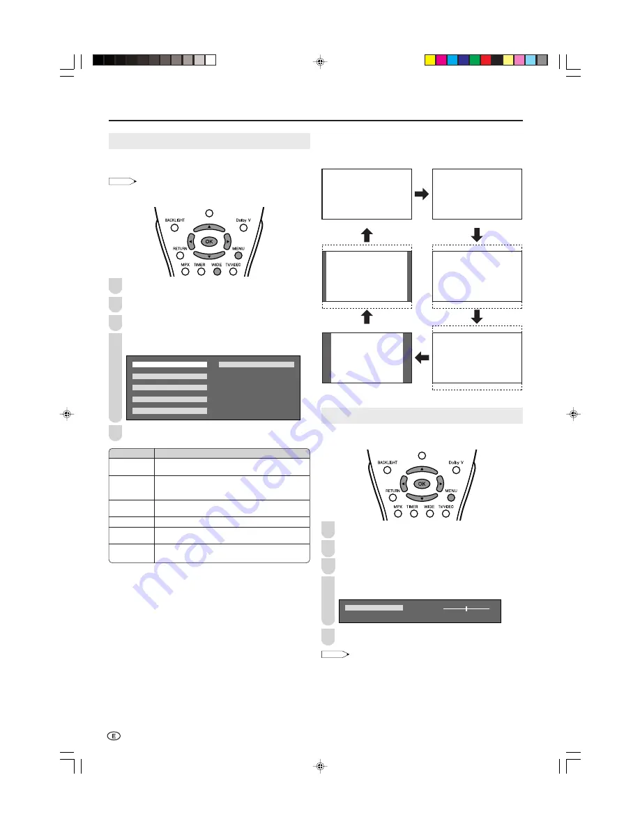
WIDE MODE

You can select the picture display size for the playback
image of the DVD player.

NOTE

• “WIDE MODE” cannot be set when 720P or 1080

Ι

 signal is

received from the COMPONENT terminals.

Press 

MENU

 to display the Menu screen.

Press 

\

/

|

 to select “FEATURES”.

Press 

'

/

"

 to select “WIDE MODE”, and press 

OK

.

Press 

'

/

"

/

\

/

|

 to select the desired mode, and press

OK

.

    N O R M A L                   C I N E M A   1 4 : 9

    Z O O M   1 4 : 9

    P A N O R A M A

    F U L L

    C I N E M A   1 6 : 9

Press 

MENU

 to exit.


Directly setting the Wide mode

Press 

WIDE

 to display the Wide mode screen.

• Each time you press

 WIDE

, the mode changes as follows.

V-POSITION (Vertical Position)

Adjusting a picture’s vertical position.

Press 

MENU

 to display the Menu screen.

Press 

\

/

|

 to select “FEATURES”.

Press 

'

/

"

 to select “V-POSITION”, and press 

OK

.

Press 

\

/

|

 to adjust the item to your desired position.

• Centres the image by moving it up or down.

  V - P O S I T I O N

  [       ] –                 +

0

Press 

MENU 

to exit.

NOTE

• You can adjust a different vertical position for each input mode

(COMPONENT, AV1, AV2, AV3 and TV).

WIDE MODE [NORMAL]

WIDE MODE [ZOOM 14:9]

WIDE MODE [PANORAMA]

WIDE MODE [FULL]

WIDE MODE [CINEMA 14:9]

WIDE MODE [CINEMA 16:9]

Selected item

NORMAL

ZOOM 14:9

PANORAMA

FULL

CINEMA 16:9

CINEMA 14:9

Description

For 4:3 “standard” pictures. A side bar appears on
each side.

For 14:9 letterbox pictures. A thin side bar appears
on each side, and you may also see bars on the
top and bottom with some programmes.

In this mode the picture is progressively stretched
toward each side of the screen.

For 16:9 squeeze pictures.

For 16:9 letterbox pictures. Bars may appear on the
top and bottom with some programmes.

For 14:9 letterbox pictures. Bars may appear on the
top and bottom with some programmes.

1

2

3

4

5

1

2

3

4

5

LC-22GA3H_E_P19-25.p65

04.9.2, 1:53 PM

22

Summary of Contents for AQUOS LC-22GA3H

Page 1: ...rinted in Japan TINS B559WJZZB 04P10 JKM Printed on 100 post consumer recycled paper SHARP CORPORATION LCD COLOUR TELEVISION LC 22GA3H OPERATION MANUAL ENGLISH LC 22GA3H_E_Hyo1_4 p65 2004 10 14 2 11 PM 1 ...

Page 2: ... Setting MANUAL 14 CLOCK SETUP 14 Selecting Menu Items 15 Basic Adjustment Settings 16 BOOSTER 16 AV MODE 16 Picture Adjustments 16 COLOUR SYSTEM AV1 AV2 or AV3 Mode 17 Colour Temperature 17 I P SETUP 18 DNR Digital Noise Reduction 18 FILM MODE 18 QUICK SHOOT 18 Useful Features 19 Sound Adjustments 19 SPEECH EMPHASIS 19 DOLBY VIRTUAL 19 DISPLAY MODE 20 AV3 IN OUT 20 On Screen Display Language Sett...

Page 3: ... the same reason do not spill water or liquid on the product 10 Servicing Do not attempt to service the product yourself Removing covers can expose you to high voltage and other dangerous conditions Request a qualified service person to perform servicing 11 Repair If any of the following conditions occurs unplug the AC cord from the AC outlet and request a qualified service person to perform repai...

Page 4: ... bookcase or rack unless proper ventilation is provided or the manufacturer s instructions are followed The LCD panel used in this product is made of glass Therefore it can break when the product is dropped or applied with impact Be careful not to be injured by broken glass pieces in case the LCD panel breaks Heat sources Keep the product away from heat sources such as radiators heaters stoves and...

Page 5: ...vided with the LCD TV set Supplied Accessories LC 22GA3H Operation manual Remote control AAA size batteries 2 AC adapter pages 5 and 9 page 5 page 6 Antenna cable page 6 AC cord page 6 Cable clamps 2 page 8 LC 22GA3H_E_P01 09 p65 04 9 3 11 09 AM 4 ...

Page 6: ... rash If chemical leakage is found wipe it off with a cloth The batteries supplied with the LCD TV set may have a shorter operating time due to storage conditions If the remote control is not to be used for an extended period of time remove the batteries from the remote control Preparation Engaging the lower claw with the remote control close the cover Using Remote Control Use the remote control b...

Page 7: ...lfunction Do not wrap or cover the AC adapter with a blanket or similar covering This can cause a malfunction or accident Do not attempt to disassemble or modify the AC adapter The insides of the AC adapter contain high voltage components that can result in the risk of electrical shock NOTE Use a commercially available AC plug adapter if necessary depending on the design of the wall outlet Always ...

Page 8: ... wake up timer is set POWER indicator The POWER indicator lights up green when the power is on and red when in the standby mode the indicator will not light when the main power is off To change the vertical angle of the LCD TV set tilt the screen up to 5 degrees forward or 10 degrees backward The LCD TV set can also be rotated up to 25 degrees to right and left Please adjust the angle so that the ...

Page 9: ...AUDIO R PB CB PR CR AUDIO R AUDIO L VIDEO AV IN1 AV IN2 AV IN3 OUT AUDIO R AUDIO L VIDEO AUDIO R AUDIO L VIDEO S VIDEO How to fix the cables Secure cables and cords with the supplied cable clamps so that they do not get caught when mounting the cover Cable clamps Pull down the hook to open the cover LC 22GA3H_E_P01 09 p65 04 10 15 10 15 AM 8 ...

Page 10: ...N Returns to the previous screen Upwards Downwards Selection P 14 POWER P 10 BACKLIGHT Selects the brightness and OPC of the display P 21 TIMER Displays the Timer functions Menu screen P 23 CH P 11 WIDE Changes the wide image mode P 22 TV VIDEO Switches the input source between COMPONENT AV1 AV2 AV3 and TV mode P 10 Dolby V Selects Virtual Dolby Surround settings P 19 DISPLAY Turns on the status d...

Page 11: ...NOTE COMPONENT Select this mode when viewing the signals from the video equipment connected to the COMPONENT terminal AV1 Select this mode when viewing the signals from the video equipment connected to the AV IN1 terminal The S VIDEO terminal is additionally provided for the AV IN1 terminal If both S VIDEO terminal and VIDEO terminal are connected with cables the S VIDEO terminal takes priority AV...

Page 12: ... not be made Changing channels with CH on the remote control Press CH and the channels change in the order shown below 1 2 3 98 99 0 1 2 3 Press CH and the channels change in the order shown below 3 2 1 0 99 98 3 2 1 Using A A A A A Flashback Press A A A A A to switch the currently tuned channel to the previously tuned channel Press A A A A A again to switch back to the currently tuned channel Sou...

Page 13: ...le TV stations Make sure the antenna cable is properly connected Upper control panel 2 1 Press MENU PRESET 1 on the upper part of the LCD TV set for more than 2 seconds to display the AUTO mode screen AUTO B G VHF 1 48 25MHZ Press VOL PRESET 2 on the upper part of the LCD TV set All the TV stations in your area that can be received by the LCD TV set are automatically preset The screen shows whatev...

Page 14: ... not have been set correctly if noise can be heard or if there is no sound In such a case adjust SOUND SYSTEM See page 14 Presetting the Channels MANUAL In a weak reception area or under bad reception conditions Upper control panel 4 1 2 3 5 Press MENU PRESET 1 on the upper part of the LCD TV set for more than 2 seconds to display the AUTO mode screen Press MENU PRESET 1 to display the MANUAL mode...

Page 15: ...E 8 7 1 1 M H Z N I C A M O F F A 2 O F F 0 Each time you press the setting for individual items changes as shown in the table on the right Press MENU to exit 1 2 4 5 NOTE Switching Colour system Set the system to Auto for normal TV reception The Auto mode automatically detects the receiving signal system and changes the reception system of the LCD TV set When the picture or sound is not stable sw...

Page 16: ... N T T I N T S H A R P N E S S S H A R P N E S S C O L O U R S Y S T E M A D V A N C E D R E S E T 0 0 0 0 0 PICTURE SOUND SETUP FEATURES Menu setting screens For details on setting each menu item refer to the page number indicated below NOTE The illustrations and on screen displays in this manual are for explanation purposes and may vary slightly from the actual appearance Depending on the settin...

Page 17: ... D Y N A M I C C O N T R A S T 3 C O N T R A S T 3 B R I G H T N E S S B R I G H T N E S S C O L O U R C O L O U R T I N T T I N T S H A R P N E S S S H A R P N E S S C O L O U R S Y S T E M A D V A N C E D R E S E T 0 0 0 0 0 Press to adjust the item to your desired position Press MENU to exit NOTE Select COLOUR SYSTEM and press OK to select AUTO PAL SECAM N358 N443 or PAL60 See page 17 Select AD...

Page 18: ...ce Press MENU to display the Menu screen Press to select PICTURE Press to select ADVANCED and press OK Press to select COLOUR TEMP and press OK 0 0 0 C O L O U R T E M P R E D G R E E N B L U E I P S E T U P D N R F I L M M O D E Q U I C K S H O O T R E S E T Press to select the desired item and press OK U S E R H I G H M I D D L E L O W Press MENU to exit When you select USER the following items ...

Page 19: ... a clear picture with Progressive Especially suitable for media with special effects like game software Normally you should select this setting 2 3 1 3 2 4 FILM MODE Automatically detects a film based source originally encoded at 24 frames second analyses it and then recreates each still film frame for high definition picture quality Perform steps 1 to 3 in I P SETUP to display the ADVANCED screen...

Page 20: ... cannot be set when the headphone mini plug is plugged into headphone jack Speech emphasis does not work when sound is output from the headphones DOLBY VIRTUAL You can enjoy the Surround 2ch stereo with Dolby Pro Logic ΙΙ technology Virtual Dolby Surround is a technology certified by Dolby Laboratories that creates a virtualised surround sound experience from two speakers using Dolby Pro Logic or ...

Page 21: ...A B C ABC ABC 4 2 1 AV3 IN OUT You can select the AV IN3 OUT terminal as input terminals or output terminals Press MENU to display the Menu screen Press to select SETUP Press to select AV3 IN OUT and press OK Press to select the desired mode and press OK I N O U T O U T Press MENU to exit NOTE AV3 IN OUT cannot be set when AV3 is selected as an input mode or AV3 is selected in CHANNEL of WAKE UP T...

Page 22: ...lly disappears after 3 seconds See the table above for details of each backlight setting When set to AUTO OPC make sure that no object obstructs the OPC sensor which could affect its ability to sense surrounding light 1 4 2 5 Selected item AUTO OPC BRIGHT NORMAL DARK Description Screen brightness is adjusted according to the ambient light of the room Maximum brightness Brightness 60 Suitable for v...

Page 23: ... OK Press to adjust the item to your desired position Centres the image by moving it up or down V P O S I T I O N 0 Press MENU to exit NOTE You can adjust a different vertical position for each input mode COMPONENT AV1 AV2 AV3 and TV WIDE MODE NORMAL WIDE MODE ZOOM 14 9 WIDE MODE PANORAMA WIDE MODE FULL WIDE MODE CINEMA 14 9 WIDE MODE CINEMA 16 9 Selected item NORMAL ZOOM 14 9 PANORAMA FULL CINEMA...

Page 24: ...o select WAKE UP TIMER and press OK Press to select the desired adjustment item and press to adjust them S E T O F F W A K E U P T I M E C H A N N E L C H 1 V O L U M E 2 0 0 0 0 Press MENU to exit NOTE When you set WAKE UP TIMER the WAKE UP TIMER indicator lights up red Be sure to adjust the clock with CLOCK SETUP in SETUP before setting WAKE UP TIMER You can output the picture and sound of the e...

Page 25: ...setting can be selected individually for each channel number When stereo sound is received When monaural sound is received NICAM Broadcast Selection When main sound is selected When sub sound is selected When monaural sound is selected If the sound quality is poor due to a weak signal or other problems during NICAM broadcast reception set the OFF position of the NICAM to change the TV sound to mon...

Page 26: ...o a weak signal or other problems during A2 stereo broadcast reception set the OFF position of the A2 to change the TV sound to monaural Press MENU to display the Menu screen Press to select SETUP Press to select CH SETUP and press OK Press to select MANUAL and press OK Press to select A2 and press to select OFF When the A2 sound is set to the OFF position the TV sound is output in monaural When t...

Page 27: ...nput terminals VIDEO and S VIDEO When you connect external devices to both terminals and if you select AV IN1 you can only view pictures from the S VIDEO terminal To view the picture from the VIDEO terminal do not connect any external devices to the S VIDEO terminal For more information about external device connections see the manuals of your external devices Example Camcorder Home video game sys...

Page 28: ... through the AV output terminals AV IN3 OUT When using AV IN3 OUT as an OUTPUT terminal select SETUP in the Menu and set AV3 IN OUT to OUT See page 20 The factory setting for AV3 IN OUT is IN NOTE The AV IN3 OUT terminal has 2 output modes see page 20 When using the S VIDEO input for AV IN1 no video output will be made to the AV output terminal but audio output will be made for connection to exter...

Page 29: ...y cause improper operation In this case operate the unit after first turning the power off or unplugging the AC cord and re plugging it in after 1 or 2 minutes Reference page Picture There is no picture or sound There is no picture There is no picture from AV IN1 2 3 There is no sound The picture is not clear The picture is too light or improp erly tinted The picture is too dark Remote control doe...

Page 30: ... systems World multi system TV Standard CCIR PAL B G I D K NTSC M SECAM B G D K TV Tuning System Auto preset tuning TV function STEREO BILINGUAL NICAM B G I D K A2 stereo B G AUTO PRESET Yes CATV S1 S41 ch Hyper Band 4 LINE DIGITAL COMB FILTER Yes Brightness 450 cd m2 Lamp life 60 000 hours Viewing angles H 170 V 170 Audio output 5 W 2 Speakers 6 12 cm 2 pcs COMPONENT Y PB CB PR CR Audio L R AV IN...

Page 31: ...30 Unit mm 384 212 567 100 490 including rubber foot 175 353 439 496 including rubber foot 272 476 244 178 86 63 90 100 43 9 Dimensional Drawings LC 22GA3H_E_P26 30 p65 04 8 25 8 49 PM 30 ...

Page 32: ...MEMO LC 22GA3H_E_P26 32 p65 04 9 15 5 44 PM 31 ...

Page 33: ...MEMO LC 22GA3H_E_P26 32 p65 04 9 15 5 44 PM 32 ...

Reviews: