background image

36

AH-N45DP2
AU-N45DP2
AH-N56DP2
AU-N56DP2

A

B

C

D

E

F

G

H

A

1

2

3

4

5

6

1

2

3

4

5

6

B

C

D

E

F

G

H

'2003. 03

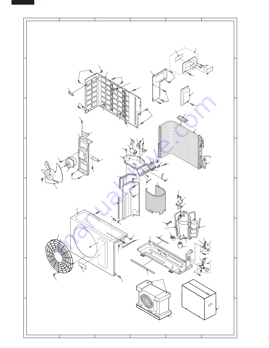
OUTDOOR UNIT AU-N45DP2 / AU-N56DP2

6-4

6-4

6-4

6-4

6-4

6-4

6-3

6-4

6-3

6-4

2-10

1-7

1-14

6-4

6-4

6-5

1-24

3-2

1-6

1-30

1-20

1-22

1-4

6-3

6-3

6-3

1-1

1-1

1-3

1-2

6-4

6-2

6-3

1-8

1-23

6-3

1-26

1-13

1-25

1-29

1-16

6-1

3-7

3-8

3-10

1-28

3-11

1-12

6-3

6-3

6-3

6-3

1-21

1-10

1-9

2-2

2-7

2-6

6-8

6-7

1-27

1-19

1-5

1-18

1-11

6-10

2-8

2-4

2-5

2-1 6-8

2-9

6-3

3-4

3-3

3-6

1-15

7-3

7-1

7-2

Fro

nt s

ide

3-14

6-6

3-5

3-12

3-15

2-3

3-1

3-13

3-9

Summary of Contents for AH-N45DP2

Page 1: ... original condition and only parts identical to those specified should be used SPLIT SYSTEM ROOM AIR CONDITIONERS AU N45DP2 AU N56DP2 TABLE OF CONTENTS Page SPECIFICATIONS 2 EXTERNAL DIMENSIONS 3 WIRING DIAGRAMS 4 ELECTRICAL PARTS 5 MICROCOMPUTER CONTROL SYSTEM 6 FUNCTIONS 10 TROUBLESHOOTING GUIDE OF CONTROL CIRCUIT 16 REFRIGERATION CYCLE 20 PERFORMANCE CURVES 21 REFRIGERANT PIPE INSTALLATION WORK...

Page 2: ...70g Capillary tube size Outer dia mm 3 2 3 5 Inner dia mm 2 0 2 2 Length mm 400 800 Q ty 1 1 Noise level High dB A 40 52 44 54 at cooling Med dB A 36 39 Low dB A 34 37 Fan system Drive Direct drive Air flow quantity High m3 min 15 3 48 18 1 50 at cooling Med m3 min 13 4 15 0 Low m3 min 11 3 13 7 Fan Cross flow fan Propeller fan Cross flow fan Propeller fan Connections Refrigerant coupling Flare ty...

Page 3: ...2 122 320 342 890 290 37 30 172 25 62 46 3 10 5 ø4 5 EXTERNAL DIMENSIONS Figure E 1 INDOOR UNIT Figure E 2 OUTDOOR UNIT 220 1600 Power supply cord Length unit mm 325 1040 Remote controller 58 18 5 22 140 TEMP INVERTER AIR CONDITIONER TEMP MODE FAN TIMER ...

Page 4: ... N45DP2 室内機 室外機 黒 藍 端子板 端子板 機 組 間 配 線 L 電源 單相 端子板 茶 藍 緑 黄 風扇馬達 電容器 回轉數 檢出信号 風扇馬達 紅 黒 藍 導風板 馬達 室温用 恒温器 熱交用 恒温器 控 制 基 板 受信基板 指示 基板1 指示基板2 指示基板3 電源變厭器 保險絲 内部温度控制器 内部 温度 控制器 In Out 2 5或3A 400或430V 内部清洗按鈕2 内部清洗按鈕1 離子簇 産生器 注意 高厭電 蒸發器 CB806 L 電源 單相 機組間配線 端子板 緑 黄 紅 黒 内部温度控制器 風扇馬達 黒 藍 藍 風扇馬達電容器 藍 紅 白 運轉電容器 内部過載継電器 厭縮機 370 或 400V 35μF 控制接地 ...

Page 5: ...機 端子板 端子板 機 組 間 配 線 茶 L 電源 單相 端子板 緑 黄 藍 藍 紅 茶 保險絲 控 制 基 板 風扇馬達 電容器 藍 黒 紅 回轉數 檢出信号 内部 温度 控制器 風扇馬達 導風板 馬達 室温用 恒温器 熱交用 恒温器 内部温度控制器 電源變厭器 指示 基板1 受信基板 指示基板3 指示基板2 2 5或3A 250V 400或430V 内部清洗按鈕1 内部清洗按鈕2 離子簇 産生器 注意 高厭電 蒸發器 L 電源 單相 機組間配線 端子板 黄 茶 藍 緑 黄 内部温度控制器 風扇馬達 黒 藍 藍 風扇馬達電容器 藍 運轉電容器 白 紅 藍 紅 黒 内部過載継電器 厭縮機 継電器 CB807 370 或 400V 35μF 控制接地 ...

Page 6: ...hermal Protector Cut off 135 10 C Internal 7 Power Supply Rating 20A 250V 12AWG Cord Type SJT12AWGSJT12 12AWGX3 8 Louver Motor Rating DC12V 250 Type MP35EA Part Part Name Items Specifications No AU N45DP2 AU N56DP2 1 Terminal Board Rating 300V 25A 2 Fan motor Rating 450V 3µF 450V 3µF Capacitor 3 Running Rating 370V or 400V 35µF 370V or 400V 35µF Capacitor 4 Compessor Rating AC208 230V 60Hz 1250W A...

Page 7: ...680 10K 10K 10 µ 16V 16V 10 µ 10k F 10K F 4 3 2 1 TH2 PIPE TEMP 15kΩ 25 C TH1 ROOM TEMP 10kΩ 25 C FAN MOTOR 2µ 1 3 5 2 7K F D7 35V 1000µ 50V 0 1µ 7812 IC2 25V 47µ 7805 0 1µ IC3 25V 10V 100µ C7 D1 4 GND 22 6K F 3 3K 4 5 IC8 1 2 3 8 7 6 0 1µ 25V 16V 0 01µ TR1 C1 C2 C3 C4 C5 C6 C8 C9 C11 C13 C14 C15 C17 C18 C19 C20 C21 C23 C25 R7 R8 R9 R10 R13 R14 R15 R16 R18 R19 R20 R21 R22 R23 R24 R25 R26 R32 R34 1...

Page 8: ...FB441 2 TO TERMINAL BOARD TOP N TO TERMINAL BOARD TOP N TO TERMINAL BOARD BOTTOM N FROM TERMINAL BOARD TOP 1 BLACK FROM TERMINAL BOARD BOTTOM L BROWN FROM FAN MOTOR FROM FAN MOTOR FROM CLUSTER GENERATOR FROM CLUSTER GENERATOR FROM CLEANING SWITCH 1 FROM CLEANING SWITCH 2 FROM THERMISTOR FROM LOUVER MOTOR BCN101 BCN201 ...

Page 9: ... 62 61 60 59 58 57 56 55 54 53 52 P44 P43 P42 P41 P40 P37 P36 P35 P34 P33 P32 P31 P64 P63 P62 P61 P60 AVR AN7 AN6 AN5 AN4 AN3 AN2 AN1 AN0 P47 P46 P45 19 18 17 16 15 14 13 12 11 10 9 8 7 6 5 4 3 2 1 Vcc 20 21 22 23 24 25 26 27 28 29 30 31 32 RST MOD0 MOD1 X0 X1 P27 P26 P25 P24 P23 P22 P21 FRONT OSC1 SSR1 0 01µ 1K JP4 JP5 16V 0 01µ 400V PATTERN SIDE IC1 50V 1µ 0 1µ 25V 13K 13K 10K 3 IC6 1 MB89537A N...

Page 10: ...FB441 2 FB441 2 TO TERMINAL BOARD TOP N TO TERMINAL BOARD TOP N TO TERMINAL BOARD BOTTOM N TO TERMINAL BOARD TOP 2 TO TERMINAL BOARD BOTTOM L FROM FAN MOTOR FROM FAN MOTOR FROM CLUSTER GENERATOR FROM CLUSTER GENERATOR FROM CLEANING SWITCH 1 FROM CLEANING SWITCH 2 FROM THERMISTOR FROM LOUVER MOTOR BCN101 BCN201 ...

Page 11: ...V 26 P27 IN 27 P26 OUT FAN MOTOR A CONTROL 28 P25 OUT OUTDOOR FAN M CONTROL 29 P24 OUT VALVE CONTROL 30 P23 OUT COMPRESSOR CONTROL 31 P22 OUT BUZZER 32 P21 OUT CLUSTER GENERATOR CONTROL Pin Terminal Input No Name Output Function 33 P20 IN CLEANING SW1 34 P17 OUT LOUVER MOTOR 35 P16 OUT LOUVER MOTOR 36 P15 OUT LOUVER MOTOR 37 P14 OUT LOUVER MOTOR 38 P13 NC 39 P12 NC 40 P11 NC 41 P10 NC 42 P07 OUT L...

Page 12: ...eset temperature automatically The preset temperature ranges from 18 C to 32 C When the room temperature is below 18 C the preset temperature is set to 18 C and when the room temperature is over 32 C the preset temperature is set to 32 C Dry operation is divided into three zones Cooling zone Dehumidifying zone and Circulating zone by thermostat lines D1 to D3 and the compressor and the fan motor a...

Page 13: ...ration operation starts before 0 to 30 minutes depends on the room temperature so that preset temperature is obtaind at set time 6 2 ONE HOUR TIMER When ONE HOUR timer is set the unit turns off automatically after one hour The one hour timer operation has priority over other time operation such as the TIMER ON and TIMER OFF If the ONE HOUR TIMER button is pressed again during operation the unit wi...

Page 14: ...ration the unit will restart in the same operation mode as before after power recovery 12 Test mode Keep pushing the AUX buttons and supply the power the system will go to the test mode In this mode the output of operation is switched by pushing the AUX button in the unit or the button in the remote controller Normal outputs are shown in Table Y 6 and Y 7 13 Plasma cluster Plasma cluster ion mode ...

Page 15: ...N OFF ON ON ON ON OFF OFF OFF OFF ON OFF OFF OFF OFF OFF ON ON ON ON AH N45DP2 7 42 C ON 2 45 C ON 7 C 42 C OFF 2 C 45 C OFF 0 3V 4 5V ON 0 3V 4 5V ON 0 3V 4 5V ON 0 3V 4 5V ON 0 3V 4 5V 0 1V 4 9V OFF OFF 0 3V 4 5V OFF 0 3V 4 5V OFF 0 3V 4 5V OFF OFF ON OFF ON ON OFF ON ON ON OFF ON ON ON OFF OFF ON ON OFF ON ON ON OFF OFF OFF ON OFF ON Sweat JP3 DEICE 1 Pipe 1 ON OFF ON OFF ON ON OFF OFF OFF FAN ...

Page 16: ...oller and switch on the indoor unit Using a tester measure the voltage between anodes of D1 and D2 on PWB ass y Is the measured value approx 17 5 Vac Replace the PWB with a new one Is the WPE1 open circuit Replace the fuse and varistor with new ones Replace the transformer with a new one YES NO Check the cleaning switch 2 1 CN9 CN8 and lead wires Replace the cleaning switch 2 1 or reset connector ...

Page 17: ...ith a new one Does beep sound from the indoor unit Using a tester measure the voltage between terminals of resistor R26 on the PWB ass y Push the button Are batteries of the wireless remote controller proper Replace the batteries with new ones Replace the wireless remote controller When the signal is received does the voltage change Replace the PWB with a new one PWB is normal Inspect the outdoor ...

Page 18: ... terminal board 100 80 60 40 20 0 10 0 10 20 30 40 Resistance Thermistor Room temperature Heat exchange Color Yellow Orange To measure the resistance first remove the connector as shown at right Room temperature thermistor TH1 Tester Connector No 3 to 4 No 1 to 2 Fig 1 Temperature properties of indoor thermistors K Heat exchange thermistor TH2 orange 25 C resistance 15 K Room temperature thermisto...

Page 19: ...itor may be defective Push the button AUX on the indoor unit for more than 5 sec Is the voltage between terminal of black lead wire on the relay in the outdoor unit and terminal N on the terminal board the power suuply voltage Are the resistances conformed Fig 1 Replace the thermistor ass y with a new one NO YES YES NO Replace the PWB ass y with a new one Using a tester measure voltage at the term...

Page 20: ... valve Accumulator Indoor side Outdoor side Temperature C Temperature C Relative humididity Relative humididity 27 47 35 40 Cooling ISO condition Dimension of Capillary tube AH N45DP2 AH N56DP2 Cooling Cooling Model NO Condition Based on ISO 5151 1994 E condition T1 at 220V refrigerant pipes length 7 5m 1 2 3 4 Service port pressure 83 C 81 C 40 C 37 C 11 C 11 C 7 C 4 C 0 46MPa 0 46MPa O D I D L C...

Page 21: ... CURVES MODEL AH N56DP2 PIPE SIZE GAS LIQUID STANDARD PERMISSIBLE LENGTH STANDARD LEVEL DIFERENCE 1 2 5 8 1 4 1 4 15m 10m 15m 10m AH N45DP2 4 5 5 0 5 5 Cooling capacity kW 1500 Power input W 12 Outside air temp C Inside Outlet air temp C 3 0 3 1 3 2 3 3 3 4 3 5 3 6 3 7 3 8 3 9 4 0 13 14 15 16 2000 Indoor air temp 27 C Indoor humidity 47RH Indoor fan speed Hi Pipe length 7 5m 2500 6 0 6 5 Cooling c...

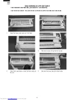
Page 22: ...T MODEL AH N45DP2 AH N56DP2 CAUTION DISCONNECT THE UNIT FROM THE POWER SUPPLY BEFORE ANY SERVICING 1 Open the Opne panel remove 2 Air Filters 2 Open the Louver frame unlook the hooks and pull the unit 3 Remove 6 screws fixing the Front panel 4 Remove the screw fixing the Cord holder ...

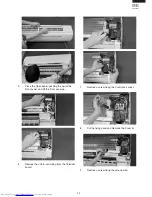
Page 23: ...n panel pushing the nail of the Front panel and lift the Front panel up 6 Remove the unit to unit wiring from the Terminal board 7 Remove a screw fixing the Control box cover 8 Cut the fixing band and Remove the Cover B 9 Remove a screw fixing the ground wire ...

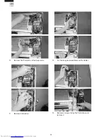
Page 24: ...AH N45DP2 AU N45DP2 AH N56DP2 AU N56DP2 10 Remove the Thermistor of the Evaporator 11 Remove Connectors 12 Cut the fixing band and Remove the Holder 13 Remove 2 screws fixing the Control box and remove it ...

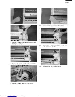
Page 25: ...n pan and pull Drain pan toward you 15 Remove the Drain cover from the Evaporator 16 Remove 3 screws fixing the Evaporator 17 Remove the Evaporator from the Cabinet 18 Remove 4 screws fixing the Side cover R and pull up the Cross flow fan 19 Loose a screw fixing Cross flow fan ...

Page 26: ...ixing the Receiving filter 2 Remove the 2 Switch and Photo detector unit 3 Remove a screw fixing the Cord holder 4 Remove a screw fixing the Cord holder and 2 screws fixing the Terminal board 5 Remove 2 screws fixing the Transformer and pull the Control board unit The DRAIN PAN and related ...

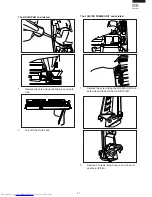
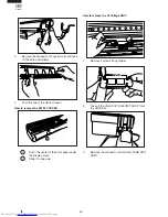
Page 27: ...ated 1 Remove the screw fixing the Drain pan on both side 2 Turn left the Drain hose The LOUVER FRAME UNIT and related 1 Remove the screw fixing the FRAME GUIDE on both side and take off the LOUVER UNIT 2 Remove 2 screws fixing Cover L and Cover R and take off them ...

Page 28: ... Push the one of the Vertical louver How to remove the DISPLY COVER 1 Push the center of the Front panel under the Display cover 2 Slide it to one side How to remove the Hi Voltage UNIT 1 Remove 2 screws fixing Holder 2 Take off the HIGH VOLTAGE UNIT ASS Y from the HOLDER 3 Remove the connector of HIGH VOLTAGE UNIT ASS Y ...

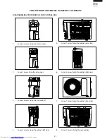
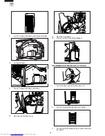
Page 29: ... 3 screws fixing the control cover 2 Loose 1 screw fixing the side cover 3 Loose 8 screws fixing the side cover R 4 Loose 2 screws fixing the cabinet left side 5 Loose 1 screw fixing the cabinet rear side 6 Loose 3 screw fixing the cabinet right side 7 Loose 1 screw fixing the cabinet front side 8 Loose 7 screws fixing the rear cabinet ...

Page 30: ...d 11 Loose 1 screw fixing the control box 12 Remove the terminal cover 13 Remove 3 terminals 14 Loose 3 screws fixing the bulkhead DISASSEMBLING PROCEDURE OF THE FAN 1 Loose the fan nut and fan can take out 2 Loose 2 screw fixing the fan motor angle 3 Cut the nylon band and loose 4 screws fixing the fan motor ...

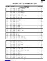
Page 31: ...HLD A536JBFA Holder 1 AM 1 36 LHLD A277JBF0 Tube holder 1 AD 1 37 PCOV A819JBEZ Cover 1 AA 1 38 PCOV A820JBEZ Cover B 1 AB 1 39 LHLD A548JBFA Holder 1 AM 1 40 LHLD A549JBFA Holder 1 AM 1 41 QW VZE167JBZZ Lead wire 1 AM 1 42 PFPFPC205JBEZ Filter insulator 2 AA 1 43 TSPC E396JBRA Name label AH N45DP2 1 AE 1 43 TSPC E397JBRA Name label AH N56DP2 1 AE 1 44 TLABCB734JBRZ Wiring diagram AH N45DP2 1 AD 1...

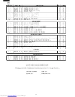
Page 32: ...LV A238JBEZ Flare union 1 2 AH N56DP2 1 AM 3 6 DEVA A188JBKZ Evaporator sub assembly AH N45DP2 1 CA 3 6 DEVA A203JBKZ Evaporator sub assembly AH N56DP2 1 BW ACCESSORY PARTS 4 1 CRMC A607JBEZ Remote control 1 BA 4 2 UBATUA027JBE0 Battery pack 1 AE 4 3 LHLD A535JBFA Cord holder for covering the terminal board of indoor unit 1 AE 4 4 XTTSD40P20000 Tapping screw for fixing the cord holder 1 AA 4 5 LX ...

Page 33: ... 14 2 11 2 19 2 20 1 39 1 40 2 6 1 38 1 29 1 1 1 7 2 9 2 9 2 15 1 10 1 33 1 15 1 21 1 19 1 12 1 10 1 10 1 33 1 35 2 15 1 41 2 7 1 9 1 8 1 22 1 14 1 13 1 13 1 11 1 9 1 9 1 16 1 17 2 18 2 8 1 32 1 34 2 13 2 12 2 17 2 16 1 28 1 5 4 7 3 6 1 31 1 30 3 1 5 1 3 4 2 5 2 1 1 37 1 6 1 4 2 4 3 5 3 3 3 2 1 42 1 31 1 31 1 31 1 42 1 36 6 3 6 2 6 1 4 2 4 9 4 8 4 4 4 5 4 6 4 12 4 10 4 1 4 3 1 20 1 3 4 11 ...

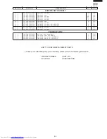
Page 34: ...A Cord clamp holder 1 AG 2 3 QW IZA031JBZZ Compressor cord 1 AT 2 4 RC HZA472JBZZ Running capacitor 1 AX 2 5 RC HZA404JBZZ Fan motor capacitor 1 AU 2 6 QTANZA002JBZZ Terminal board AU N45DP2 1 AN 2 6 QTANZA001JBZZ Terminal board AU N56DP2 1 AQ 2 7 LHLD A539JBFA Cord clamp 1 AE 2 8 PBOX A379JBWZ Control box 1 AR 2 9 LBNDKA047JBW0 Capacitor clamp 1 AH 2 10 TLABCB806JBRZ Wiring diagram AU N45DP2 1 AE...

Page 35: ...3 LX BZA140JBE0 Special screw 24 AB 6 4 LX BZA292JBE0 Special screw 19 AC 6 5 LX BZA166JBE0 Special screw 1 AB 6 6 LX NZA048JBE0 Special nut 4 AA 6 7 XCPSD40P25000 Tapping screw 1 AC 6 8 XCTSD40P12000 Tapping screw AU N45DP2 2 AA 6 8 XCTSD40P12000 Tapping screw AU N56DP2 4 AA 6 9 XCTSD40P40000 Tapping screw 2 AA 6 10 LX BZA075JBE0 Special screw 1 AA PACKING PARTS 7 1 CPADBA050JBKZ Bottom pad assem...

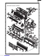
Page 36: ...3 6 4 6 3 6 4 2 10 1 7 1 14 6 4 6 4 6 5 1 24 3 2 1 6 1 30 1 20 1 22 1 4 6 3 6 3 6 3 1 1 1 1 1 3 1 2 6 4 6 2 6 3 1 8 1 23 6 3 1 26 1 13 1 25 1 29 1 16 6 1 3 7 3 8 3 10 1 28 3 11 1 12 6 3 6 3 6 3 6 3 1 21 1 10 1 9 2 2 2 7 2 6 6 8 6 7 1 27 1 19 1 5 1 18 1 11 6 10 2 8 2 4 2 5 2 1 6 8 2 9 6 3 3 4 3 3 3 6 1 15 7 3 7 1 7 2 Front side 3 14 6 6 3 5 3 12 3 15 2 3 3 1 3 13 3 9 ...

Reviews: