14
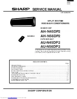
AH-N45DP2
AU-N45DP2
AH-N56DP2
AU-N56DP2
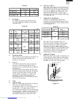
Timer LED
(Yellow)
ON
OFF
Judgement
Normal
(Generator OK)
Failure
(Check circuit)
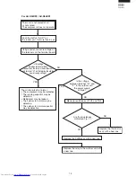
1) Cluster generator checking (STEP 1)
9.
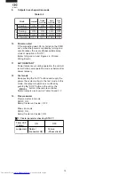
Outputs in each operation mode
Table H-4
10.
Power on start
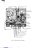
If the connecting wire JP5 is shorten on the PWB
ass'y, when the power is supplied by turning on a
circuit breaker, the air conditioner automatically
starts of operation in "AUTO".
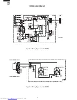
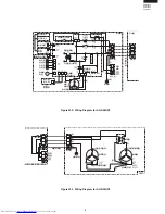
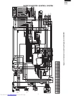
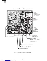
(Refer to Figure L-2.and Figure L-4. Printed
Wiring Board.)
11.
AUTO RESTART
Power failure occurs during operation, the unit will
restart in the same operation mode as before after
power recovery.
12.
Test mode
Keep pushing the "AUX." buttons and supply the
power, the system will go to the test mode. In this
mode, the output of operation is switched by
pushing the "AUX." button in the unit or the
"
" button in the remote controller.
Normal outputs are shown in Table Y-6 and Y-7.
13.
Plasma cluster
Plasma cluster ion mode
SSR2 : ON
Relay (Cluster unit inside) : OFF
Minus ion mode
SSR2 : ON
Relay (Cluster unit inside) : ON
ON
OFF
ON
OFF
ON
ON
OFF
OFF
ON
OFF
ON
ON
ON
L/UL
UL/D
OFF
D/OFF
OFF
OFF
OFF
Mode
Compressor
Outdoor
Fan Motor
Cooling
Circulating
Indoor
Fan Motor
Valve
Coil
C
O
O
L
D
R
Y
Cooling
Circulating
Dehumidiflying

