ENG-
E-17
1
2
3
4
5
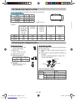
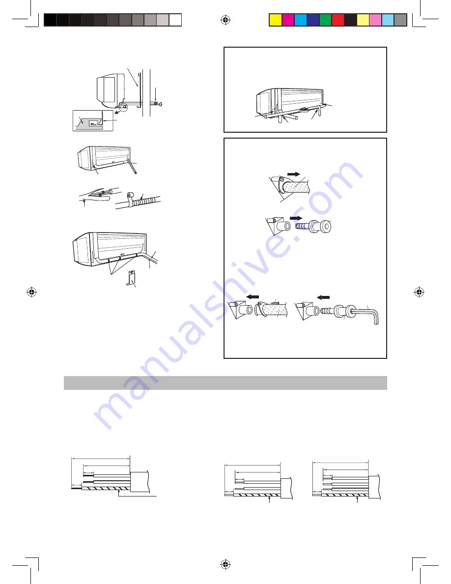
(1) Remove the screw and pull out the drain hose.
(2) Pull out the drain cap.
(3) Reconnect the drain hose to the right and
insert the drain cap to the left.
• Fully insert the drain hose until it stops
and fix the screw removed in (1).
• Insert a hexagon wrench (4 mm diagonal)
into the drain cap, and press it fully.
Drain Hose
Hexagon wrench
Drain Cap
Drain Hose
Drain Cap
Screw
Exchange the drain hose
Screw
CONNECTING THE CABLE TO THE INDOOR UNIT
Use a copper cable. (Cross-section area: 2.0 mm
2
) 9,000-12,000-18,000 BTU only
Use a cable which is not lighter than polychloroprene sheathed flexible cord (Code designation 60245 IEC 57).
Use a copper cable. (Cross-section area: 2.0 mm
2
) 24,000 BTU only
8
8
40
50
Earth wire
Connecting cable
Length unit: mm
8
8
80
90
8
8
80
90
Drain Hose
MOUNTING PLATE
Taping
Drain Cap
Hook
MOUNTING PLATE
Piping holder
Tape
Pipes
Drain Hose
Insulation
Tape
Earth wire
Earth wire
Plate
Cut the plate along notch.
Piping route
For directions 1, 2 , 4 and 5, cut out the specific
zone without leaving any sharp edge.
(Keep the cut-out plate for possible future use.)
Model 18000/24000 BTU
Model 9000/12000 BTU
Model 18000 BTU
Model 24000 BTU
Plate
Plate
Plate
WARNING:
After replacing, make sure that both the drain
hose and drain cap are firmly inserted.
OM_AH-PN10 13GY_EN.indd Sec1:17
OM_AH-PN10 13GY_EN.indd Sec1:17
12/22/11 6:30:32 PM
12/22/11 6:30:32 PM

