background image

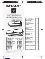
OPERATION MANUAL

 INDOOR UNIT      OUTDOOR UNIT

AH-PN10 AU-PN10

AH-PN10-GY AU-PN10

AH-PN13 AU-PN13

AH-PN13-GY AU-PN13

AH-PN19 AU-PN19

AH-PN24 AU-PN24

AH-L10 AU-L10

AH-L13 AU-L13

CONTENTS

Page

IMPORTANT SAFETY 
INSTRUCTIONS

1

PART NAMES

2

USING THE REMOTE 
CONTROL

5

AUXILIARY MODE

5

TIPS ON SAVING 
ENERGY

5

BASIC OPERATION

6

ADJUSTING THE AIR 
FLOW DIRECTION

7

POWERFUL JET 
OPERATION

7

GENTLE COOL AIR

8

PLASMACLUSTER 
OPERATION

8

TIMER OPERATION

9

ONE-HOUR OFF TIMER

10

DISPLAY BUTTON

10

MAINTENANCE

11

OPERATING CONDITION

11

BEFORE CALLING FOR 
SERVICE

12

INSTALLATION MANUAL

13

AH-PN10, 10GY  AH-L10

AH-PN13, 13GY  AH-L13

AH-PN19, AH-PN24

INSTALLATION MANUAL

Thank you for purchasing a SHARP air conditioner.
Please read this manual carefully before operating
the product

OM_AH-PN10 13GY_EN.indd   1

OM_AH-PN10 13GY_EN.indd   1

12/22/11   6:30:07 PM

12/22/11   6:30:07 PM

Summary of Contents for AH-L10

Page 1: ...NG THE AIR FLOW DIRECTION 7 POWERFUL JET OPERATION 7 GENTLE COOL AIR 8 PLASMACLUSTER OPERATION 8 TIMER OPERATION 9 ONE HOUR OFF TIMER 10 DISPLAY BUTTON 10 MAINTENANCE 11 OPERATING CONDITION 11 BEFORE CALLING FOR SERVICE 12 INSTALLATION MANUAL 13 AH PN10 10GY AH L10 AH PN13 13GY AH L13 AH PN19 AH PN24 INSTALLATION MANUAL Thank you for purchasing a SHARP air conditioner Please read this manual caref...

Page 2: ...OM_AH PN10 13GY_EN indd 2 OM_AH PN10 13GY_EN indd 2 12 22 11 6 30 09 PM 12 22 11 6 30 09 PM ...

Page 3: ... CAUTIONS Open a window or door periodically to ventilate the room especially when using gas appliances Insufficient ventilation may cause oxygen shortage Do not operate the buttons with wet hand It may cause electric shock For safety turn the circuit breaker off when not using the unit for an extended period of time Check the outdoor unit mounting rack periodically for wear and to make sure it is...

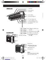
Page 4: ... Lamp blue PART NAMES INDOOR UNIT OUTDOOR UNIT 1 2 3 4 5 6 7 8 9 10 11 13 14 15 16 13 Inlet Air 14 Refrigerant Pipe and Interconnecting Cord 15 Drainage Hose 16 Outlet Air NOTE Actual units might vary slightly from those shown above AH L10 AH L13 9 10 11 AH PN10 AH PN10 GY AH PN13 AH PN13 GY AU PN10 AU PN13 AU L10 AU L13 12 OM_AH PN10 13GY_EN indd Sec1 2 OM_AH PN10 13GY_EN indd Sec1 2 12 22 11 6 3...

Page 5: ...ed 12 TIMER Lamp orange 13 POWERFUL JET Lamp blue 14 Inlet Air 15 Refrigerant Pipe and Interconnecting Cord 16 Drainage Hose 17 Outlet Air NOTE Actual units might vary slightly from those shown above INDOOR UNIT OUTDOOR UNIT 1 2 3 4 5 6 7 8 9 14 15 16 17 14 15 16 17 AU PN19 AU PN24 10 11 12 13 AH PN19 AH PN24 OM_AH PN10 13GY_EN indd Sec1 3 OM_AH PN10 13GY_EN indd Sec1 3 12 22 11 6 30 11 PM 12 22 1...

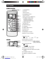
Page 6: ...E Symbols AUTO COOL DRY 18 POWERFUL JET Symbol 19 PLASMACLUSTER Symbol 20 FAN SPEED Symbols AUTO Manual setting 21 GENTLE COOL AIR Symbol 22 TEMPERATURE AND TIMER COUNT DOWN Indicator 23 TRANSMITTING Symbol 24 TIMER ON TIMER OFF Indicator 17 18 19 20 21 22 23 24 1 2 3 4 5 6 7 8 9 10 11 12 13 14 15 16 PART NAMES AH PN10 AH PN10 GY AH PN13 AH PN13 GY AH PN19 AH PN24 ONLY AH PN10 AH PN10 GY AH PN13 A...

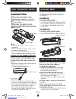
Page 7: ...ct sunlight or near a heater Protect the remote control from moisture and shock Use this mode when the remote control is not available TO TURN ON Press the AUX button The red OPERATION lamp will light and the unit will start operating in the AUTO mode The fan speed and temperature setting are set to AUTO TO TURN OFF Press the AUX button again The red OPERATION lamp will turn off AUXILIARY MODE TIP...

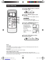
Page 8: ...set the desired fan speed BASIC OPERATION AUTO COOL DRY AUTO SOFT LOW HIGH NOTE AUTO MODE In the AUTO mode the temperature setting and mode are automatically selected according to the room temperature when the unit is turned on DRY MODE The fan speed is preset to AUTO and cannot be changed WHEN POWER FAILURE OCCURS This air conditioner has a memory function to store settings when a power failure o...

Page 9: ...re lever 1 2 1 9 000 12 000 BTU 18 000 24 000 BTU CAUTION Never attempt to adjust the vertical airflow lou vre manually Manual adjustment of the vertical airflow lou vre can cause the unit to malfunction When the vertical adjustment louvre is posi tioned at the lowest position in the COOL or DRY mode for an extended period of time condensation may result VERTICAL AIR FLOW DIRECTION 1 Press the SWI...

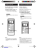
Page 10: ... During operation press the PLASMACLUSTER button The remote control will display The blue PLASMACLUSTER lamp will light up TO CANCEL Press the PLASMACLUSTER button again The blue PLASMACLUSTER lamp will turn off NOTE Use of the PLASMACLUSTER operation will be memorized and it will be activated the next time you turn on the unit To perform Plasmacluster operation in FAN only mode press the PLASMACL...

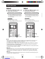
Page 11: ...and TIMER ON can not be set together The ONE HOUR OFF TIMER operation has priority over TIMER ON and TIMER OFF operations When the temperature is set during timer setting the temperature will show in the display for 5 seconds and then return to the timer display If a power failure occurs while the TIMER is set the TIMER setting will be cancelled and will not be retrieved even after the power is re...

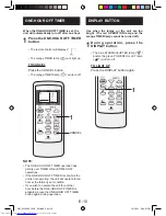
Page 12: ...g the unit will operate for an hour at the formerly set condition If you wish to operate the unit for another hour before the ONE HOUR OFF TIMER is activated press the ONE HOUR OFF TIMER button again during operation ONE HOUR OFF TIMER Use when the lamps on the unit are too bright The red OPERATION lamp and the orange TIMER lamp cannot be turned off 1 During operation press the DISPLAY button The ...

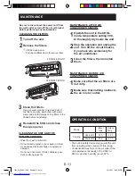
Page 13: ... setting 30 C to thoroughly dry inside the unit 2 Stop the operation and unplug the unit Turn off the circuit breaker if you have one exclusively for the air conditioner 3 Clean the filters then reinstall them MAINTENANCE BEFORE AIR CONDITIONER SEASON 1 Make sure that the air filters are not dirty 2 Make sure that nothing obstructs the air inlet or outlet 3 Clean the filters Use a vacuum cleaner t...

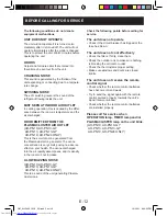
Page 14: ...changed This is to protect the unit Wait 3 minutes before operating the unit ODORS Carpet and furniture odors that entered into theunit may be sent out from the unit CRACKING NOISE This sound is generated by the friction of the unit expanding or connecting due to a tempera ture change SWISHING NOISE The soft swishing noise is the sound of the refrigerant flowing inside the unit MIST SEEN AT INDOOR...

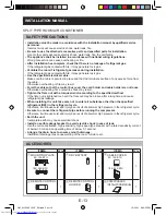
Page 15: ...ee of any excess force from the cable Otherwise overheating or fire may result Form the cable so that the control box cover the cord holder and cable holder are not loose Otherwise overheating fire or electric shock may result Tighten the flare nut with a torque wrench according to the specified method If the flare nut is tightened too hard the flare nut may be broken after a long time and cause r...

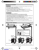
Page 16: ...d result 5 Keep TV set radio and the like 1 m or more away from the unit 6 Avoid locations exposed to machine oil vapor salty air facing the seashore for example hot spring vapor sulfur gas etc Such location can cause breakdown 7 Avoid locations exposed to muddy water along a road for example or where the unit can be tampered with 8 Select a location where the outgoing air or operating noise canno...

Page 17: ...provide a trap near the hose s lead in port Use the refrigerant pipes shown in the table below Pipe size Pipe thickness Thermal insulation Liquid side 1 4 ø 6 35 mm 0 8 mm Thickness 6 mm or thicker Material Polyethylene foam Gas side 9K Btu h type 3 8 ø 9 52 mm 12K Btu h type 1 2 ø 12 7 mm 18K 24K Btu h type 5 8 ø 15 88 mm 1 0 mm The thermal insulation should cover both the gas and liquid pipes Tr...

Page 18: ...the unit to check that the unit is fixed in place For left side piping 1 Reverse the positions of the drain hose and drain cap Refer to Exchange the drain hose 2 Connect the pipes and wrap tape around the insula tion of the piping joints tightly not to become thick 3 Bind the pipes and connecting cable with tape 4 Set the pipes and connecting cable along the back of the unit and attach the piping ...

Page 19: ...thed flexible cord Code designation 60245 IEC 57 Use a copper cable Cross section area 2 0 mm2 24 000 BTU only 8 8 40 50 Earth wire Connecting cable Length unit mm 8 8 80 90 8 8 80 90 Drain Hose MOUNTING PLATE Taping Drain Cap Hook MOUNTING PLATE Piping holder Tape Pipes Drain Hose Insulation Tape Earth wire Earth wire Plate Cut the plate along notch Piping route For directions 1 2 4 and 5 cut out...

Page 20: ...ap allowed Not to rise Connecting the drain hose 1 Connect a drain hose 2 Tape over the connecting part Drain Hose Commercially available ø16 mm No trap allowed NOTE Be sure to lay the drain hose downward for smooth drainflow Be careful not to allow the drain hose to rise form a trap or leave its end in water as shown below Coil thermal insulation around a drain hose extension if run ning in the r...

Page 21: ...flare nuts by hand for the first 3 4 turns 2 Use a wrench and torque wrench to tighten up the pipes Do not over tighten the pipes It may be de formed or damaged Flaring the pipe end 1 Cutting with a pipe cutter Cut at a right angle 2 Deburring Allow no cuttings in the pipe 3 Putting in the flare nut 4 Flaring the pipe end Flare processing dimensions A Tool A R22 tool 0 5 1 0 mm 5 Checking To be fl...

Page 22: ...efrigerant pipe and cable 3 Remove the pipe cover Pipe cover front 4 Connect the pipes Align the center of the pipes and tighten the flare nuts by hand for the first 3 4 turns Use two wrenches to tighten up the pipes Take care so that the connecting pipes will not touch the internal refrigerant piping Be sure to cover the pipe connection area thoroughly with pipe thermal insulation Slit 6 Fill up ...

Page 23: ... the vacuum pump for 10 15 minutes Make sure the compound gauge reads 0 1 MPa 76 cmHg 5 Close the gauge manifold valve 6 Turn off the vacuum pump Leave as it for 1 2 minutes and make sure the needle of the compound gauge does not go back 7 Open the 2 way valve 90 counterclockwise by turning the hexagon wrench Close it after 5 second and check for gas leakage 8 Disconnect the gauge manifold hose fr...

Page 24: ...องถอดฝาชุดครอบท อออก ถอดรูสําหรับต อสายไฟออก โดยกระแทกที แผ นเหล กของถอดฝาชุดครอบท อออก 2 ต อสายไฟเข ากับชุดควบคุมโดยต อให ตรงกับที ต อกับชุดภายในบ าน 2 ต อสายไฟเข ากับชุดควบคุมโดยต อให ตรงกับที ต อกับชุดภายในบ าน 3 ยึดสายไฟให แนนด วยตัวยึดสายไฟ 3 ยึดสายไฟให แนนด วยตัวยึดสายไฟ 4 Double check that the cable is securely in place 5 ป ดช องว างระหว างสายไฟและรูของแผ นให หมดเพื อป องกันสิ งแปลกปลอมเข า...

Page 25: ...on lamp flashes 3 Make sure the system runs well To stop the operation press the AUX button again ITEMS TO CHECK Is the specified power supply voltage used Is the connecting cable fixed to terminal board firmly Is the earth wire connected properly arranged Is the drainage properly Is the indoor unit hooked to the mounting plate firmly Is there any gas leakage at the pipe connection EXPLANATION TO ...

Page 26: ... almost 0 MPa 0 cmHg 5 Stop the test run operation 6 Disconnect the gauge manifold hose from the service port 7 Disconnect both refrigerant pipes PROCEDURE WITHOUT USING GAUGE MANIFOLD 1 Run the air conditioner at cooling test run mode Refer to TEST RUN 2 After 5 10 minutes fully close the 2 way valve by turning the hexagon wrench 3 After 2 3 minutes immediately close the 3 way valve fully 4 Stop ...

Page 27: ...OM_AH PN10 13GY_EN indd Sec1 25 OM_AH PN10 13GY_EN indd Sec1 25 12 22 11 6 30 42 PM 12 22 11 6 30 42 PM ...

Page 28: ...Printed in Thailand TINSEA720JBRZ 11M TH 2 OM_AH PN10 13GY_EN indd Sec1 26 OM_AH PN10 13GY_EN indd Sec1 26 12 22 11 6 30 42 PM 12 22 11 6 30 42 PM ...

Reviews: