
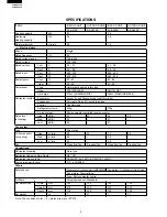
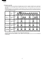


AY/AE-A079E
AY/AE-A099E
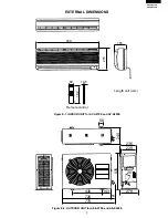
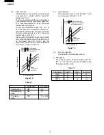
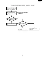
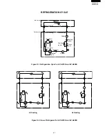
7
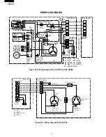
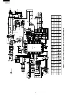
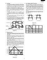
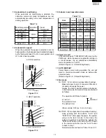
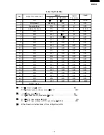
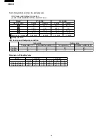
Figure L-2. Printed Wiring Board
Thermistor
CN7
CN6
CN101
CN201
Indoor fan motor(R.P.M. Signal)
Indoor fan motor
Terminal board L
Terminal board " 1 "
Transformer
BCN2
BCN1
TRANSFORMER
Louver motor
Fan motor capacitor
Fan motor capacitor
250V2.5A
FUSE
IN
OUT
R
Y1
R
Y3
R
Y2
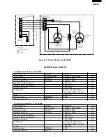
DPWBF
A
JBK0(P)
QPWBFB252JBE0(P)
R3
R26
R41
R40
C23
C13
R28
IC2
R29
JP46
D9
CN6
C22
C21
C20
R20
R15
R16
R21
R39
R25
OUT
IN
8
1
1
1 3
3
QPWBFB252JBE0(C)
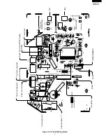
DPWBFA
JBK0(C)
R2
C2
D5
CNR3
C8
C7
C12
C4
C9
IC3
JP49
CT
JP 27
JP42
CN3
CN5
CN4
JP44
JP43
OSC
IC5
JP9
JP48
JP47
R11
R12
R8
R9
R35
C15
R10
C101
SW201
TEST
R
UN
A
UX.
SW202
CN101
CN201
LED101
LED102
RECEIVER UNIT
QPWBFB124JBE0
QPWBF
A652JBE0
OPERA
TION
(RED)
TIMER
(YELLO
W)
JP3
JP2
JP6
R36
R34
R32
R31
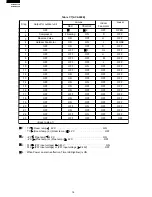
MODEL A
MODEL B
FAN H
FAN M
FAN L
WIRELESSL
D
. F
AN OFF
12H / 24H
OFF WIDEH
DEICE B
DEICE A
RPM PULSE
SWEA
T
CN7
C5
C3
CN1
FAN
LOUVER
IN
OUT
MO
TOR
RPM SIGNAL
THERMIST
OR
MO
TOR
GRA
Y
(B)
SSR
R6
D4
1
1
8
2
5
7
2
7
13
11
51
1
3
11
1
4
5
8
19
52
64
33
16
9
8
1
IC4
D2
D1
CN2
BCN1
(TRANSFORMER)
L
C1
NR
FAN MO
TOR
CAP ACIT
OR
(D)
CNR1
CNR2
VAL
VE
PURPLE
ORANGE
OUT DOOR
FAN MO
TOR(F)
(E)
2
COIL
(C1)
(A1)
BLUE
(FAN MO
TOR CAP
ACIT
OR)
D3
1
5
5
1
1
1
1 1
1
6
3
3
5
JP38
JP39
IC1
POWER ON
FREEZE A
FREEZE B
DE.FAN A
DE.FAN B
JP8
JP11
JP13
JP14
R7
R23
R24
JP50
JP33
JP4
JP5
JP7
R19
JP10
C19
C16
R4
Q3
Q2
R22
JP12
JP51
BCN2 JP35
JP41
JP40
R38
R37
R33
JP1
PREHEAT
JP34
C14
C18
JP37
JP36
IC6
C17
FPWBF
A134JBK0
FPWBF
A013JBK0
FSGY -A141JBK0
3
1
Q1
C6
C10
R30
R18
R17
C11
R5
20
1
1
3
5
R14
R13
D7
D8
GND
12V
GND
5V
12V
3
DIP
DIP


