40
61R-WP5H
55R-WP5H
Adjustment procedure
(1) Start adjustment at the center of the screen.
(2) Continue adjustment at next closest position.
(3) Adjust center area first, and ending with edge sections.
(4) Press the INPUT button to perform interpolation operation.
This process will take about 1 second and no picture will be seen at this time.
(5) After interpolation, check convergence again and repeat (1)-(5) if necessary.
(6) When convergence is acceptable, press D to write data to ROM memory. ROM WRITE? is displayed to alarm
system that ROM will be overwritten with new data. Press the D button again to write displayed data to ROM.
(7) DATA WRITE TO ROM will take approximately 4 seconds and no picture will be displayed.
(8) Green dots will be displayed when operation is complete.
(9) Press MUTE or any button (A,B,D MENU INPUT and AV Mode) to return to convergence pattern, then confirm
again convergence is acceptable.
(10) Press INPUT for 3 seconds more, convergence adjustment mode will be returned to C01 of service mode.
Notes: (1) Display only green for easier adjustment and match to jig screen. Press "ENTER", THEN PRESS 100/
ENT. (Use green to set raster position and correct for distortions.)
(2) Perform interpolation and data write to ROM after green adjustment. Once green has been confirmed to
match jig screen, the jig screen can be removed. Do not readjust the green color after jig screen has
been removed. This is now your reference color.
(3) Display green and red only and match red to green.
(4) Display all colors and match blue to green and red.
Touch-up red color if necessary.
(5) Existing DATA in ROM can be read by pressing the C button 2 times. This data can be used after
replacing a component (CRT, DY, etc.) Where complete convergence adjustment is not necessary be
careful not to overwrite this data.
DO NOT write cleared RAM data into ROM or a complete convergence adjustment will be necessary.
Remember to try with Existing data before starting convergence adjustment to minimize adjustment
time.
(6) Access for (3x3) mode. With the TV set off (AC Line off) Short circuit the located S6501 using a wire,
and then press the power button (AC line on before press). This operation will clear.
Note : All stored convergence data settings.
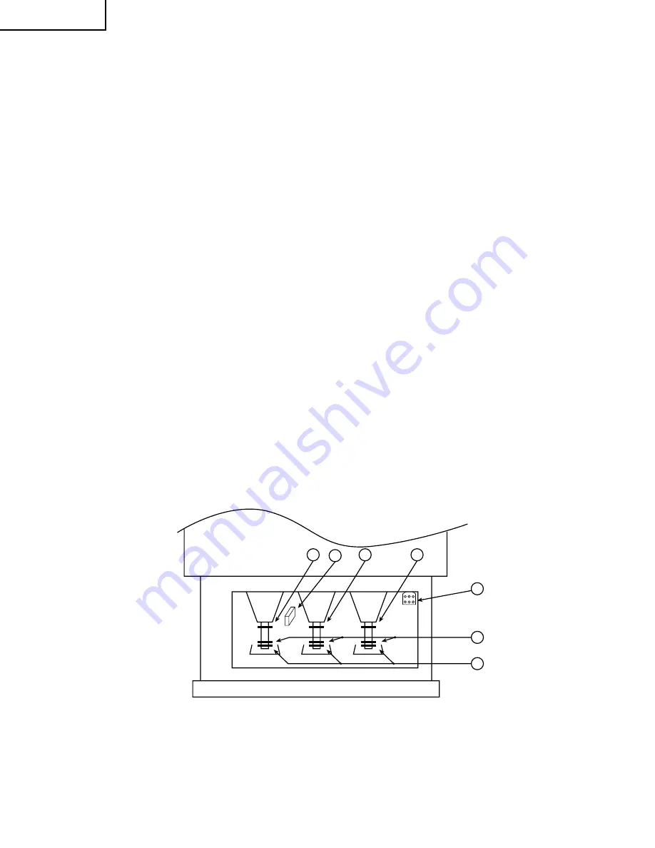
ADJUSTMENT POINT
CRT, cabinet locations
1. CENTERING MAGNET FOR RED CRT
2. CENTERING MAGNET FOR GREEN CRT
3. CENTERING MAGNET FOR BLUE CRT
4. 4-POLE MAGNET FOR BEAM SHAPE ADJUSTMENT
5. BEAM ALIGNMENT MAGNET
6. DIGITAL CONVERGENCE MODULE
7. FOCUS PACK (TOP ADJUSTMENT FOR SCREEN, BOTTOM FOR FOCUS)
1
2
3
7
4
BLUE
GREEN
RED
FRONT OF TV
5
6
Summary of Contents for 55R-WP4H
Page 5: ...1 2 3 4 5 6 7 8 9 10 11 12 13 14 15 16 17 18 19 20 A B C D E F G H I J MAIN UNIT 3 5 6 7 ...
Page 50: ...42 6 5 4 3 2 1 A B C D E F G H 61R WP5H 55R WP5H CHASSIS LAYOUT 1 4 ...
Page 51: ...43 6 5 4 3 2 1 A B C D E F G H 61R WP5H 55R WP5H CHASSIS LAYOUT 2 4 ...
Page 52: ...44 6 5 4 3 2 1 A B C D E F G H 61R WP5H 55R WP5H CHASSIS LAYOUT 3 4 ...
Page 53: ...45 6 5 4 3 2 1 A B C D E F G H 61R WP5H 55R WP5H CHASSIS LAYOUT 4 4 ...
Page 54: ...47 61R WP5H 55R WP5H 46 12 11 10 9 8 7 6 5 4 3 2 1 A B C D E F G H BLOCK DIAGRAM ...
Page 57: ...51 6 5 4 3 2 1 A B C D E F G H 61R WP5H 55R WP5H Ë CRT RED UNIT ...
Page 58: ...52 6 5 4 3 2 1 A B C D E F G H 61R WP5H 55R WP5H Ë CRT GREEN UNIT ...
Page 59: ...53 6 5 4 3 2 1 A B C D E F G H 61R WP5H 55R WP5H Ë CRT BLUE UNIT ...
Page 60: ...55 61R WP5H 55R WP5H 54 12 11 10 9 8 7 6 5 4 3 2 1 A B C D E F G H Ë MAIN UNIT 1 5 ...
Page 61: ...57 61R WP5H 55R WP5H 56 12 11 10 9 8 7 6 5 4 3 2 1 A B C D E F G H Ë MAIN UNIT 2 5 ...
Page 62: ...59 61R WP5H 55R WP5H 58 12 11 10 9 8 7 6 5 4 3 2 1 A B C D E F G H Ë MAIN UNIT 3 5 ...
Page 63: ...61 61R WP5H 55R WP5H 60 12 11 10 9 8 7 6 5 4 3 2 1 A B C D E F G H Ë MAIN UNIT 4 5 ...
Page 64: ...63 61R WP5H 55R WP5H 62 12 11 10 9 8 7 6 5 4 3 2 1 A B C D E F G H Ë MAIN UNIT 5 5 ...
Page 65: ...65 61R WP5H 55R WP5H 64 12 11 10 9 8 7 6 5 4 3 2 1 A B C D E F G H Ë H V UNIT ...
Page 66: ...67 61R WP5H 55R WP5H 66 12 11 10 9 8 7 6 5 4 3 2 1 A B C D E F G H Ë 3D Y C SEPARATE UNIT ...
Page 67: ...69 61R WP5H 55R WP5H 68 12 11 10 9 8 7 6 5 4 3 2 1 A B C D E F G H Ë AUDIO UNIT ...
Page 68: ...71 61R WP5H 55R WP5H 70 12 11 10 9 8 7 6 5 4 3 2 1 A B C D E F G H Ë POWER UNIT ...
Page 69: ...72 6 5 4 3 2 1 A B C D E F G H 61R WP5H 55R WP5H Ë SUB POWER UNIT ...
Page 70: ...73 6 5 4 3 2 1 A B C D E F G H 61R WP5H 55R WP5H Ë CONTROL UNIT ...
Page 71: ...75 61R WP5H 55R WP5H 74 12 11 10 9 8 7 6 5 4 3 2 1 A B C D E F G H Ë CONVERGENCE DRIVER UNIT ...
Page 72: ...77 61R WP5H 55R WP5H 76 12 11 10 9 8 7 6 5 4 3 2 1 A B C D E F G H Ë TUNER UNIT ...
Page 73: ...79 61R WP5H 55R WP5H 78 12 11 10 9 8 7 6 5 4 3 2 1 A B C D E F G H Ë VCJ UNIT 1 2 ...
Page 74: ...81 61R WP5H 55R WP5H 80 12 11 10 9 8 7 6 5 4 3 2 1 A B C D E F G H Ë VCJ UNIT 2 2 ...
Page 76: ...85 61R WP5H 55R WP5H 84 12 11 10 9 8 7 6 5 4 3 2 1 A B C D E F G H PWB A Main Unit B Side ...
Page 77: ...87 61R WP5H 55R WP5H 86 12 11 10 9 8 7 6 5 4 3 2 1 A B C D E F G H PWB C H V Unit Wiring Side ...
Page 83: ...93 6 5 4 3 2 1 A B C D E F G H 61R WP5H 55R WP5H PWB J Power Unit Wiring Side ...
Page 84: ...94 6 5 4 3 2 1 A B C D E F G H 61R WP5H 55R WP5H PWB M Sub Power Unit Wiring Side ...
Page 86: ...96 6 5 4 3 2 1 A B C D E F G H 61R WP5H 55R WP5H PWB Q Tuner Unit A Side ...
Page 87: ...97 6 5 4 3 2 1 A B C D E F G H 61R WP5H 55R WP5H PWB Q Tuner Unit B Side ...
Page 88: ...98 6 5 4 3 2 1 A B C D E F G H 61R WP5H 55R WP5H PWB S VCJ Unit A Side ...
Page 89: ...99 6 5 4 3 2 1 A B C D E F G H 61R WP5H 55R WP5H PWB S VCJ Unit B Side ...


